E-ton 90 cc atv with no spark
#21
 11-25-2010, 06:19 PM


my kids cdi is on right side just under gas tank on frame, just above coil. The stator is on right side by shifter my kids has a screw out peep hole on plate or cover. on the top and side, also if u tare it apart becareful not to turn magneto wheel because it could through off ur timing (i think?) maybe the other guys would know more about that. I dont know much about them but i figured a little advice is better than none.
#22
11-26-2010, 12:42 AM

Electrical Expert
Likes High Voltage In The Tub!
Likes High Voltage In The Tub!
Join Date: Dec 2008
Location: Tracy, California, USA
Posts: 3,260
Likes: 0
Received 12 Likes
on
12 Posts
I think I found the CDI. It only has 5 wires coming out of it. Red that plugs into a blue on white, red on white, red on black, white on black, black. The wire diagram that I have has 6 wires coming from the CDI. But Mine only has 5. Also my wire diagram does not have a stator on it. It does have an ignition coil which has a blue on white wire and a heavy wire going to the spark plug
1) Unplug the CDI.
2) Turn on the ignition, and set all your kill (stop) switches to the "run" position.
3) Set your meter to measure resistance (ohms) on the lowest scale (like 200 ohms). Put the black lead on frame ground (making sure you get a good solid connection).
4) Measure the resistance of all five wires to ground and report what you find for each wire. If the wire reads open (infinite resistance, or the same reading as when the leads are not connected to anything), then repeat on a higher resistance scale until you get a reading.
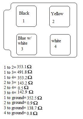
What we're trying to do is figure out what each wire color's function:
A) One of the wires should read zero ohms to ground because it is the ground wire (I'm thinking it will be the black wire).
B) One wire should read less than 1 ohm (but not zero ohms). That would be the coil (i'm thinking it will be the White/blue wire).
C) One should read about 150 ohms. That would be the trigger pickup coil from the stator (perhaps the white/red wire).
D) One wire should read appriximately 450 ohms. That would be the AC ignition power from the stator (probably Black/Red).
E) One wire should read zero ohms to ground, but if you turn off the ignition or press the stop switch it will read open (infinite ohms). That would be the Kill switch wire (probably black/white).
Not only will this help with indentifying the wires but if any of the five functions above don't ohm out correctly that gives a clue as to what to measure next.
#23
11-26-2010, 09:49 AM

Join Date: Sep 2010
Posts: 35
Likes: 0
Received 0 Likes
on
0 Posts
#26
11-26-2010, 11:47 PM
Electrical Expert
Likes High Voltage In The Tub!
Likes High Voltage In The Tub!
Join Date: Dec 2008
Location: Tracy, California, USA
Posts: 3,260
Likes: 0
Received 12 Likes
on
12 Posts
I think I found the CDI. It only has 5 wires coming out of it. Red that plugs into a blue on white, red on white, red on black, white on black, black. The wire diagram that I have has 6 wires coming from the CDI. But Mine only has 5. Also my wire diagram does not have a stator on it. It does have an ignition coil which has a blue on white wire and a heavy wire going to the spark plug
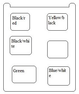
It is inside the engine, so what you want to look for is wires coming out of the engine side cover.
Here is a copy of a eton thunder 90 wiring diagram (click on the picture for a larger version that is still too small):

Obviously it is wrong since you have 5 wire on the CDI - not six. The stator is just to the left of the CDI on the bottom of the picture. Is this the same diagram that you have?
#27
11-26-2010, 11:59 PM
Electrical Expert
Likes High Voltage In The Tub!
Likes High Voltage In The Tub!
Join Date: Dec 2008
Location: Tracy, California, USA
Posts: 3,260
Likes: 0
Received 12 Likes
on
12 Posts
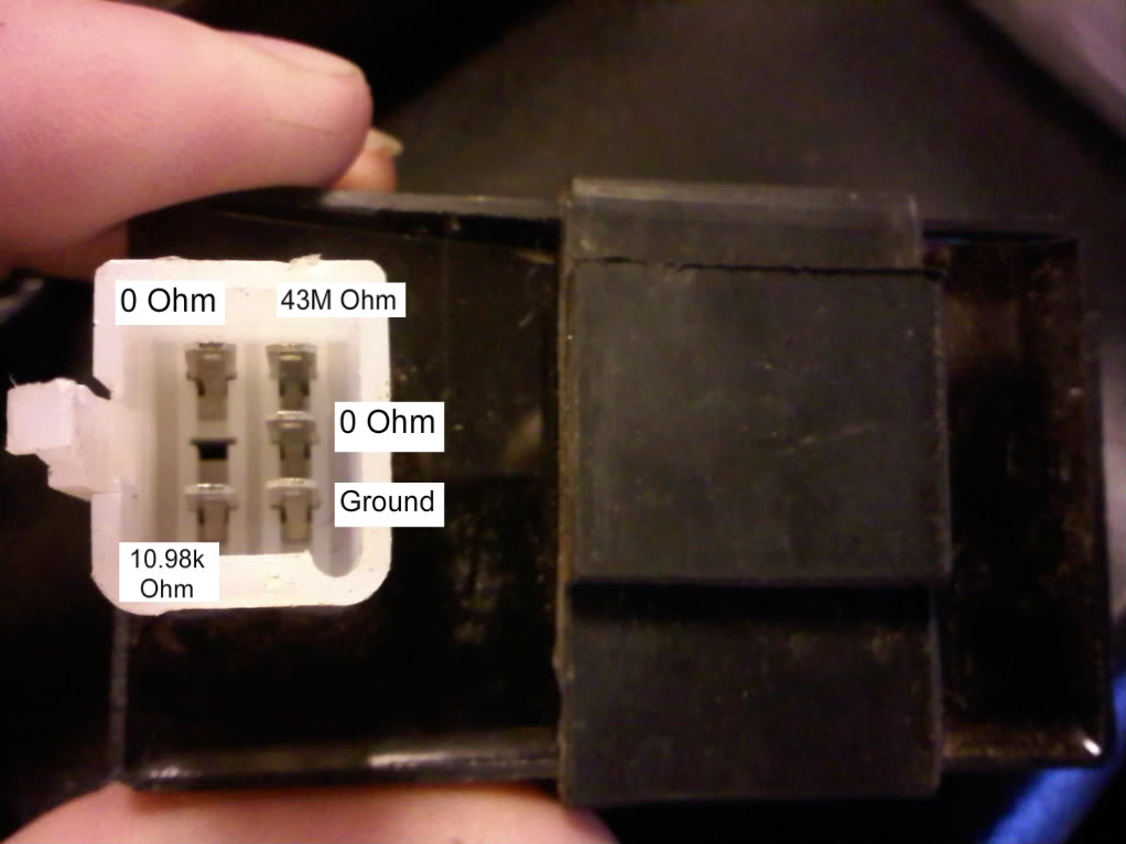
Also, the readings don't make sense even if they are looking into the CDI module. Could you recheck those readings again? In particular make sure the two top most pins in the picture (labeled 0 Ohm, and 43M Ohm) are not reversed.
#28
11-27-2010, 12:18 AM
Electrical Expert
Likes High Voltage In The Tub!
Likes High Voltage In The Tub!
Join Date: Dec 2008
Location: Tracy, California, USA
Posts: 3,260
Likes: 0
Received 12 Likes
on
12 Posts


The reading you are interested in are the readings from each pin to ground. Pin 1 is the moderately high voltage AC power from the stator to the CDI (and it is more commonly black with red stripe rather than just black). Pin 3 is the trigger signal from the stator to the CDI to tell the CDI when to fire the plug.
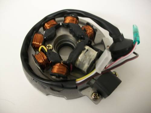
But a much better place to measure these resistances is from the CDI connector looking into the wiring harness. Then you would be measuring the AC Ignition power and trigger signal windings in the stator through the wiring harness. Thus if it reads right you know the stator windings are OK and the interconnect wiring is OK as well.
So repeat the same resistance tests but measure all the CDI pins in the wiring harness to ground. Unplug the CDI, turn on the ignition switch, and set all kill switches tothe "run" position. When you do this you will be remeasuring the trigger and AC Ignition power (assuming it is wired correctly), and you will also be measuring the ignition coil primary (though the wiring), and the kill switch circuitry.
Important Note: This is an eton thread. Eton quad kill switches and CDI wiring is different than generic Chinese quads. I believe your quad is generic chinese, so keep in mind you should read an open circuit on the kill switch pin when the kill switches are in the "run" position. Eton's on the the other hand will have this pin grounded in the "run" condition.
#29
11-27-2010, 11:21 AM
Join Date: Sep 2010
Posts: 35
Likes: 0
Received 0 Likes
on
0 Posts
#30
11-27-2010, 01:14 PM

Trailblazer
Join Date: Nov 2010
Location: Greer, SC
Posts: 33
Likes: 0
Received 0 Likes
on
0 Posts
