110 4 stroke wiring diagram wanted
#31
 12-28-2012, 04:50 PM


Lynn,
I'm following your 4-step troubleshooting guide.
1. 12.XX volts to CDI from the battery. Correct.
2. Ohms from trigger pin to ground pin = 0.L (Fluke's version of open)
3. Cranking voltage on trigger pin to ground pin = 0.02XX
From the green wire to the CDI (ground) to ground on the frame, I get 00.1 ohms (Fluke 87 auto-ranging)
Sounds like the trigger coil is bad, huh?
Doug
#32
12-28-2012, 09:30 PM

Electrical Expert
Likes High Voltage In The Tub!
Likes High Voltage In The Tub!
Join Date: Dec 2008
Location: Tracy, California, USA
Posts: 3,260
Likes: 0
Received 12 Likes
on
12 Posts
Doug,
My Comments in Blue:
My Comments in Blue:
Lynn,
I'm following your 4-step troubleshooting guide.
1. 12.XX volts to CDI from the battery. Correct. [Agreed]
2. Ohms from trigger pin to ground pin = 0.L (Fluke's version of open) [Well this is certainly wrong, but it doesn't agree with this statement you made earlier:
.
I believe the above measurement was made at the stator, not at the CDI. But those two should be the same measurement. The trigger pin at the CDI connector should be the same wire (blu/white) at the stator. 121 ohms is about right. So was the previous done in error, or is measurement being done in error, or is there a wiring problem between the CDI trigger input pin and the stator trigger signal output?]
3. Cranking voltage on trigger pin to ground pin = 0.02XX [This jives with an open trigger wire, or an open trigger coil in the stator. But again, you did measure believable trigger coil resistance earlier...]
From the green wire to the CDI (ground) to ground on the frame, I get 00.1 ohms (Fluke 87 auto-ranging) [Good]
Sounds like the trigger coil is bad, huh? [See if you read still read Open Loop (O.L. on your meter) at the stator on the 2K ohm scale.]
Doug
I'm following your 4-step troubleshooting guide.
1. 12.XX volts to CDI from the battery. Correct. [Agreed]
2. Ohms from trigger pin to ground pin = 0.L (Fluke's version of open) [Well this is certainly wrong, but it doesn't agree with this statement you made earlier:
Resistance between black and blue/white wires is 121.9 ohms
I believe the above measurement was made at the stator, not at the CDI. But those two should be the same measurement. The trigger pin at the CDI connector should be the same wire (blu/white) at the stator. 121 ohms is about right. So was the previous done in error, or is measurement being done in error, or is there a wiring problem between the CDI trigger input pin and the stator trigger signal output?]
3. Cranking voltage on trigger pin to ground pin = 0.02XX [This jives with an open trigger wire, or an open trigger coil in the stator. But again, you did measure believable trigger coil resistance earlier...]
From the green wire to the CDI (ground) to ground on the frame, I get 00.1 ohms (Fluke 87 auto-ranging) [Good]
Sounds like the trigger coil is bad, huh? [See if you read still read Open Loop (O.L. on your meter) at the stator on the 2K ohm scale.]
Doug
#33
01-08-2013, 03:00 PM
Lynn,
I had time today to pull the stator cover off. I see that the blue/white wire from the trigger coil goes out to the connector. The green wire from the trigger coil goes to ground at one of the screws that holds the stator in. Checking ohms from ground to the blue/white wire (stator & cover removed from engine) I get 123 ohms.
So, apparently, the trigger coil is good.
How does the CDI work then? Does it send a DC voltage to the ignition coil, or is it an AC voltage?
When I crank the engine, I should get some kind of voltage reading at the ignition coil, right? Can I put battery voltage to the ignition coil to test it?
Doug
#34
01-09-2013, 12:30 AM
Electrical Expert
Likes High Voltage In The Tub!
Likes High Voltage In The Tub!
Join Date: Dec 2008
Location: Tracy, California, USA
Posts: 3,260
Likes: 0
Received 12 Likes
on
12 Posts
...I had time today to pull the stator cover off. I see that the blue/white wire from the trigger coil goes out to the connector. The green wire from the trigger coil goes to ground at one of the screws that holds the stator in. Checking ohms from ground to the blue/white wire (stator & cover removed from engine) I get 123 ohms....

The CDI sends AC voltage very narrow pulses to the ignition coil. But it does this *only* if it gets a trigger signal. Here is an general analogy of what a CDI does, and how it works:
The CDI is an energy conversion device. To fire the spark plug you need a lot of power dissipated over a very small fraction of a second. To do this a special high voltage winding on the stator (AC ignition power) provides a power source that over one entire revolution of the engine charges up a storage capacitor (stores energy). At the proper time a signal from the trigger wire tells the capacitor to dump all its energy onto the ignition coil (in a fraction of a second) which produces a spark.
You know, the CDI works a lot like a standard flush toilet. After a flush, the city water pressure (think AC ignition power) comes in through a small pipe that over time and fills up a storage tank (think CDI storage capacitor). At the proper time someone wiggles a little lever (think ignition trigger signal) which flips the flapper valve open (fires the SCR inside the CDI) which causes the entire contents of the storage tank (i.e. capacitor) to get dumped into the bowl (ignition coil primary).
Another way to look at it: A birthday candle and a fire cracker contain roughly the same stored energy. One uses up its energy over a relatively long period, the other releases its energy all at once with a bang. The CDI is an energy conversion that takes in power produced from the stator (birthday candle style) over a full revolution of the engine and stores it up. Then at the proper time a trigger signal dumps the stored energy (firecracker style) onto the ignition coil primary.
No. That would destroy the ignition coil (likely with smoke, and possibly flying shrapnel). Don't do it. In the above CDI/toilet analogy, that would be akin to throwing a "firecracker" into the tank of a non functioning toilet to see if that makes it flush.
#35
01-10-2013, 01:49 PM
Lynn,
Okay, you're right, I did have an open loop between the stator wire and the CDI box wire. Here's the deal. From the CDI box, the wire is white/blue (white wire with a blue stripe). Following it, it goes to the kill switch on the left handlebar. From there, I thought it went to the stator. BUT, the wire from the stator is Blue/white (blue wire with a WHITE stripe).
Now the good part. Both wires end up under the seat where I disconnected the REMOTE kill. So, when I plugged the blue/white into the white/blue, voila, I have continuity from the CDI to the stator trigger.
The ends under the seat were male and female, so they did just plug together. That should give trigger signal to the CDI box, right?
I'll wait to hear from you, but will go ahead and install the stator/cover back on the engine.
Doug
#36
01-10-2013, 11:17 PM
Electrical Expert
Likes High Voltage In The Tub!
Likes High Voltage In The Tub!
Join Date: Dec 2008
Location: Tracy, California, USA
Posts: 3,260
Likes: 0
Received 12 Likes
on
12 Posts
Lynn,
Okay, you're right, I did have an open loop between the stator wire and the CDI box wire. Here's the deal. From the CDI box, the wire is white/blue (white wire with a blue stripe). Following it, it goes to the kill switch on the left handlebar. From there, I thought it went to the stator. BUT, the wire from the stator is Blue/white (blue wire with a WHITE stripe).
Now the good part. Both wires end up under the seat where I disconnected the REMOTE kill. So, when I plugged the blue/white into the white/blue, voila, I have continuity from the CDI to the stator trigger.
The ends under the seat were male and female, so they did just plug together. That should give trigger signal to the CDI box, right?
I'll wait to hear from you, but will go ahead and install the stator/cover back on the engine.
Doug
Okay, you're right, I did have an open loop between the stator wire and the CDI box wire. Here's the deal. From the CDI box, the wire is white/blue (white wire with a blue stripe). Following it, it goes to the kill switch on the left handlebar. From there, I thought it went to the stator. BUT, the wire from the stator is Blue/white (blue wire with a WHITE stripe).
Now the good part. Both wires end up under the seat where I disconnected the REMOTE kill. So, when I plugged the blue/white into the white/blue, voila, I have continuity from the CDI to the stator trigger.
The ends under the seat were male and female, so they did just plug together. That should give trigger signal to the CDI box, right?
I'll wait to hear from you, but will go ahead and install the stator/cover back on the engine.
Doug
Your post surprises me. You have a unique wiring setup that I have not seen before, nor do I have any wiring diagrams on any quad that resembles this. You have a DC powered ignition system which normally doesn't have remote module capability. Remember I expressed my doubt about whether you even had a four pin CDI because it was so different. Bu you convinced me down the thread that this is indeed true. Four pin CDIs do not have a kill switch input, but you can kill spark from a four pin CDI by shorting the trigger signal to ground. But in your case the kill switch seems to open the connection from the trigger signal to the CDI (also legitimate - but quite surprising to me). Hmmm...
So now can I ask you to help me
?On December 7'th in this same thread I posted some text and a wiring diagram of the generic remote wiring for a 5 pin CDI (which is AC powered). Does your DC powered remote connector have the same 9 pin connector shape as depicted in the wiring diagram? If so which pins do your blue/white and white/blue wires plug into? Assuming you do have the same 9 pin connector, and since there is no pin number scheme in the post, how about something like "my blue/white wire connects to the 'Ignition side Kill pin", and "my white/blue wire connects to 'Alarm Light 2'" (or whatever they connect to on your quad).
I'm going to have to think about this one. Any info you can provide will be greatly appreciated...
#37
01-25-2013, 02:36 PM
Lynn Edwards,
No, mine doesn't have the 9-pin connector for the remote. It has a 6-pin connector with only 4 of them used. Red, Black, Yellow/red, and Green.
Then the notorious blue/white and white/blue wires are there as well, but with their own connectors, one male and one female.
BTW, still no spark.
I did notice that although the trigger coil ohms out okay, on the AC scale, it shows 0.122 vac during cranking. You were saying that it should be upwards of 0.200 to 0.500 vac.
When I had unplugged the coil wire (black/yellow), and then plugged it back in (at the coil) I got a big spark at the connector as I put the two ends together (male female).
Wherever the problem lies, it won't spark the plug P.S., If you want to email me, I can reply back with some photos of this little animal...
My email is sturgisatv at me.com
Doug
No, mine doesn't have the 9-pin connector for the remote. It has a 6-pin connector with only 4 of them used. Red, Black, Yellow/red, and Green.
Then the notorious blue/white and white/blue wires are there as well, but with their own connectors, one male and one female.
BTW, still no spark.
I did notice that although the trigger coil ohms out okay, on the AC scale, it shows 0.122 vac during cranking. You were saying that it should be upwards of 0.200 to 0.500 vac.
When I had unplugged the coil wire (black/yellow), and then plugged it back in (at the coil) I got a big spark at the connector as I put the two ends together (male female).
Wherever the problem lies, it won't spark the plug
P.S., If you want to email me, I can reply back with some photos of this little animal...My email is sturgisatv at me.com
Doug
#38
01-29-2013, 11:27 PM
Electrical Expert
Likes High Voltage In The Tub!
Likes High Voltage In The Tub!
Join Date: Dec 2008
Location: Tracy, California, USA
Posts: 3,260
Likes: 0
Received 12 Likes
on
12 Posts
...No, mine doesn't have the 9-pin connector for the remote. It has a 6-pin connector with only 4 of them used. Red, Black, Yellow/red, and Green.
Then the notorious blue/white and white/blue wires are there as well, but with their own connectors, one male and one female....
Then the notorious blue/white and white/blue wires are there as well, but with their own connectors, one male and one female....
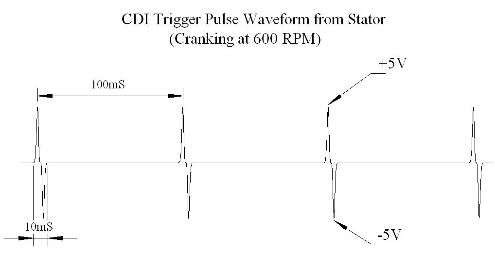
An oscilloscope is just a fancy voltmeter that can measure fast moving voltages, and display them as a function of time in graphical format. Voltage is on the Y axis, and time is on the X axis increasing from left to right. Note the plus minus narrow pulses with lots of zero volts in between. The important part is the plus and minus peaks, and not what the *average* AC voltage is, which is fairly low and what your meter will attempt to display (perhaps badly depending on the meter design).
There is another way to see if your stator is making the peak sharp pulses required to trigger your CDI if you make th following test fixture and put it across the trigger signal at the CDI to the ground pin. These three parts can all be bought cheaply at radioshack. I don't know what your wiring skills are, but the fixture will show that the necessary trigger voltages are being produced since LEDs don't conduct at all unless a 2 volt peak level is reached plus and minus. The picure specifies green LEDs, but any color will work. Green has a slightly higher threshold voltage (blue is even higher - but harder to find and more $$$), but red, yellow, orange, are all acceptable...
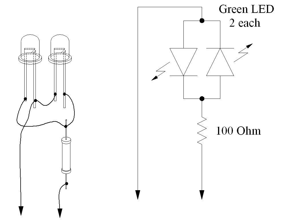
If both LEDs flash back at forth at ten times per second while cranking the quad then your trigger signal is good. Then we look after that point for problems.
I'm not sure this means anything. Your CDI internal storage capacitor is charged through the ignition coil. If you disconnect this wire while the CDI is attempting to charge the CDI storage capacitor it will spark. There is not much information there.
#39
03-18-2013, 05:25 PM
Lynn,
I haven't worked on the little quad for awhile, but today I thought I'd work it in to my schedule. Here's where I stand. (Keep in mind, how weird the wiring is on this thing...) 1. Ignition coil is new. 2. Stator and trigger coil are both new. Installed today. (New stator/trigger is 5-wires out, old one was 4-wires out. So the new one has the red/black wire for the CDI, which the old one didn't have. 3. CDI box (4-wire) new.
I still don't have any spark.
So my 4-wire CDI has the black/yellow wire going to the ignition coil. The blue/white wire coming directly from the trigger coil. The green wire is going to ground. The black wire is my hot wire @ 12.60 vdc.
Now, I didn't hook the red/black wire coming from the stator to anything, but isn't that the kill wire for the 5-wire CDI?
I need your expertise on this one....
Thanks again,
Doug

Thread
Thread Starter
Forum
Replies
Last Post
Currently Active Users Viewing This Thread: 1 (0 members and 1 guests)

