Peaces 150CC Sport ATV
#1
 04-27-2010, 12:07 PM


Join Date: Apr 2010
Posts: 8
Likes: 0
Received 0 Likes
on
0 Posts

#2
04-27-2010, 11:49 PM

Electrical Expert
Likes High Voltage In The Tub!
Likes High Voltage In The Tub!
Join Date: Dec 2008
Location: Tracy, California, USA
Posts: 3,260
Likes: 0
Received 12 Likes
on
12 Posts
Is this a GY6 150cc engine?
This could be a little tough. Look at this recent thread:
http://forums.atvconnection.com/chin...-problems.html
Scroll down to zjjeepster's post about 4 pin regulator wiring. It doesn't appear there is any standard for 4 pin regulator wiring. Worse, the regulators for some 150cc GY6 engines use the same connector for the regulator as does 110cc machines. Thes two power generating schemes are completely different and not compatible at all.
Questions:
1) Do you have a GY6 150cc engine?
2) Where did you buy the regulator? Can you post a link to where you got it?
3) Are you sure you didn't buy a 110cc four pin regulator?
If you have a GY6 engine, and you bought a GY6 regulator, and the topology inside is the standard and common "shunt style" regulating scheme (as compared to buck style), we may have a way of figuring this out. I'm not positive, but it is worth a try. It will have to wait for this weekend though for me to verify this. If my thinking is right we can use the diode junction measuring function found on most meters (it goes beep when you short the leads) to probe the bridge rectifier inside the regulator and figure out which pins are for the +/- battery connections and which pins are AC inputs. I'm still thinking about this....
Another question:
What are the colors of the wires feeding your voltage regulator?
#3
04-28-2010, 07:40 AM
Join Date: Apr 2010
Posts: 8
Likes: 0
Received 0 Likes
on
0 Posts
Best I can tell it is not a GY6 motor. I did ask the place I bought the regulator at for a wiring diagram, they did not have one. I was told it was a 150cc regulator..I have the old part and it is indeed a 4 pin regulator. I do not have the wiring colors, the ATV is at my farm..I get there on the weekend, so I'll have to get back to you on that one.
#4
05-03-2010, 04:35 AM
Join Date: Apr 2010
Posts: 8
Likes: 0
Received 0 Likes
on
0 Posts
Checked regulator colors, there is Yellow, Green, Red and White. I know where the white one goes..thats it. I was going to trace the wires..however, before I start tearing open the wire bundles, wanted to see of you had come up with anything else. I did find that the engine had a name Jing Long...was going to see if that lead me anywhere. let me know if you came up with anything...Thanks 
#5
05-03-2010, 11:51 PM
Electrical Expert
Likes High Voltage In The Tub!
Likes High Voltage In The Tub!
Join Date: Dec 2008
Location: Tracy, California, USA
Posts: 3,260
Likes: 0
Received 12 Likes
on
12 Posts
Rsarpy,
I saw your PM, and saw your last post. I just got home from a very long day and I'm totally zonked.
I *do* have info to share, but I'm fading fast tonight. If you could do me a favor to wait until tomorrow evening to post my results I'd be grateful.
I think you have a GY6 engine. Every search I have done on Peace 150cc quads, and Jinglong 150cc engines have come back Gy6. If your transmission is totally automatic (as compard to first, second, and third) then it is a GY6.
Snore... I've got to go get something to eat... Then go to bed.
#7
05-04-2010, 10:20 AM
Electrical Expert
Likes High Voltage In The Tub!
Likes High Voltage In The Tub!
Join Date: Dec 2008
Location: Tracy, California, USA
Posts: 3,260
Likes: 0
Received 12 Likes
on
12 Posts
On your wiring harness:
Yellow and White wires are the AC output wires from the stator. They go to the AC input pins on the regulator. It doesn't matter which way around they go.
Red is regulated output, Green is ground.
On your 4 pin Regulator:
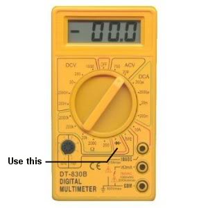
Take a meter and set it to measure diode junctions. The picture below
shows an example. Make sure your red lead is in the Volt/Ohm jack, and you black lead is in the Com jack. Polarity matters for the following tests.
Label your regulator pins 1, 2, 3, and 4. It doesn't matter how you label them just as long as you're consistent through the following tests.
Place the red lead on pin one, and probe the other three pins with the black lead. Write down what you see on each of the other three pins.
Place the red lead on pin 2. Probe pins 1, 3, and 4 with the black lead. Write down what you see for these three pins.
Place the red lead on pin 3. Probe pins 1, 2, and 4 and write the results.
Finally put the red lead on pin 4 and probe pins 1, 2, and 3.
I did this on two 150cc quads using different regulators and I got similar results. This is what I measured:
Red on pin 1:
Pin 2: Open
Pin 3: Open
Pin 4: Open
Red on pin 2:
Pin 1: 0.73
Pin 3: 0.43
Pin 4: 0.44
Red on pin 3:
Pin 1: Open
Pin 2: Open
Pin 4: Open
Red on pin 4:
Pin 1: Open
Pin 2: Open
Pin 3: Open
From the measurements find the set that doesn't read open on all the pins (red on pin 2 in the case above).
The pin with the red lead on it is ground (wire to green in your harness). The pin with the highest reading is the regulated output (wire to red in your harness). The other two pins are your AC input pins (yellow and white - it doesn't matter which way around they get wired up).
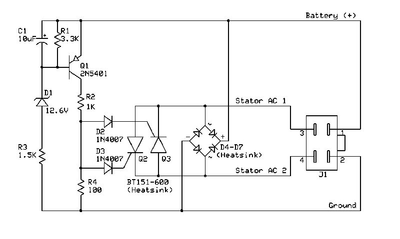
What you are doing is probing into the regulator and looking at the internal bridge rectifier. Below is a schematic of a 150cc regulator that I took apart. The bridge rectifier are diodes D4-D7. By probing all the pins with a small DC current coming from the meter on the diode measure setting, and seeing the polarity of the rectifier diodes we can identify the pins from the results.
Your pin numbers may or may not match up with the diagram below.
There are many ways to make a regulator. It is possible that your regulator uses a completely different scheme, and that the tests above will produce nonsensical results. But so far it seems to work, and I can't imagine what else they would do in the regulator front end besides using a bridge rectifier.
This test is valid only for a GY6 style regulator. 110cc quads also use a four pin regulator (same connector even). Those are completely different devices and no compatible with a Gy6 stator at all.
Finally, when wiring your regulator up make sure your battery plus wire that feeds the wiring harness is fused. That way if something gets wired wrong you'll just blow the fuse instead of melting your wiring harness.
Yellow and White wires are the AC output wires from the stator. They go to the AC input pins on the regulator. It doesn't matter which way around they go.
Red is regulated output, Green is ground.
On your 4 pin Regulator:
Take a meter and set it to measure diode junctions. The picture below
shows an example. Make sure your red lead is in the Volt/Ohm jack, and you black lead is in the Com jack. Polarity matters for the following tests.
Label your regulator pins 1, 2, 3, and 4. It doesn't matter how you label them just as long as you're consistent through the following tests.
Place the red lead on pin one, and probe the other three pins with the black lead. Write down what you see on each of the other three pins.
Place the red lead on pin 2. Probe pins 1, 3, and 4 with the black lead. Write down what you see for these three pins.
Place the red lead on pin 3. Probe pins 1, 2, and 4 and write the results.
Finally put the red lead on pin 4 and probe pins 1, 2, and 3.
I did this on two 150cc quads using different regulators and I got similar results. This is what I measured:
Red on pin 1:
Pin 2: Open
Pin 3: Open
Pin 4: Open
Red on pin 2:
Pin 1: 0.73
Pin 3: 0.43
Pin 4: 0.44
Red on pin 3:
Pin 1: Open
Pin 2: Open
Pin 4: Open
Red on pin 4:
Pin 1: Open
Pin 2: Open
Pin 3: Open
From the measurements find the set that doesn't read open on all the pins (red on pin 2 in the case above).
The pin with the red lead on it is ground (wire to green in your harness). The pin with the highest reading is the regulated output (wire to red in your harness). The other two pins are your AC input pins (yellow and white - it doesn't matter which way around they get wired up).
What you are doing is probing into the regulator and looking at the internal bridge rectifier. Below is a schematic of a 150cc regulator that I took apart. The bridge rectifier are diodes D4-D7. By probing all the pins with a small DC current coming from the meter on the diode measure setting, and seeing the polarity of the rectifier diodes we can identify the pins from the results.
Your pin numbers may or may not match up with the diagram below.
There are many ways to make a regulator. It is possible that your regulator uses a completely different scheme, and that the tests above will produce nonsensical results. But so far it seems to work, and I can't imagine what else they would do in the regulator front end besides using a bridge rectifier.
This test is valid only for a GY6 style regulator. 110cc quads also use a four pin regulator (same connector even). Those are completely different devices and no compatible with a Gy6 stator at all.
Finally, when wiring your regulator up make sure your battery plus wire that feeds the wiring harness is fused. That way if something gets wired wrong you'll just blow the fuse instead of melting your wiring harness.
Trending Topics
#9
05-17-2010, 06:41 AM
Join Date: Apr 2010
Posts: 8
Likes: 0
Received 0 Likes
on
0 Posts