2005 Yamoto 250cc Utility quad--no spark
#1
 09-14-2011, 12:07 PM


Join Date: Sep 2011
Posts: 124
Likes: 0
Received 0 Likes
on
0 Posts
This is a twin cylinder/twin carb type. I have no spark at either of the two plugs. I replaced the CDI (I shorted it out on accident--crossed some wires). Here are the checks I've done so far based on other threads I've read:
I have the pictured CDI type below and all readings are done at it's connectors
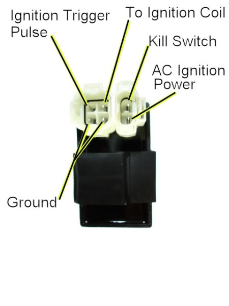
Wire colors are as follows:
2-pin plug
A/C Ign Power: Black w/red stripe
Kill Switch: White w/black stripe
4-pin plug
Ignition trigger Pulse: Blue w/yellow stripe
To Ignition Coil:Black w/yellow stripe
Ground wires (2 of them): one black w/blue stripe and one green
Here are instructions I pulled from another thread regarding no spark on a different type of quad and my test results.
Set your meter to read AC volts on the 200 volt scale. Test your meter by sticking the probes into a wall power outlet in your house. You should see about 120 volts AC. If you get that you know your meter is set up properly and working.
Now disconnect the CDI from the quad wiring harness. Measure the AC voltage on the AC ignition power pin of the wiring harness to engine ground while cranking the starter motor. That will be putting one lead on the wiring harness pin, and the other lead on the aluminum motor block. You should see 45 to 80 volts AC at normal cranking speeds. What do you measure?
A: 95.2 VAC
Set your meter to the lowest AC voltage scale that is has. 2 volts AC full scale would be ideal but many meters don't go that low. Use whatever the lowest range is, but make sure it is AC volts and not DC volts. Measure the voltage on the timing trigger pin in the wiring harness to engine ground while cranking the starter. You should see 0.2 to 0.5 volts AC. What do you measure?
Now, I assume this is the ignition trigger pulse, but again, this troubleshooting guide was for a different type CDI (single plug 6 pin)
A: Lowest setting is 200 VAC. Reading was 00.0 VAC
Set your meter to measure resistance (ohms) on the 2K ohms scale (2000 ohms). When on the resistance settings you should read zero ohms with the leads shorted, and infinite ohms when the leads are not connected together.
Turn off the quad ignition switch. Measure the AC Ignition Power pin on the wiring to engine ground with the engine sitting still (not cranking). You should see 450 ohms or so (0.450 Kohms). Measure the Timing Trigger line to ground. You should read 150 ohms or so (0.150 Kohms) with the engine sitting still. What do you measure for both of those pins?
A: 320 ohms / 149 ohms
Set your meter to the lowest resistance scale it has (20 ohms is about right).. Measure the resistance of the ground pin in the CDI to engine ground. It should read zero ohms. Measure the Ignition coil pin to engine ground. It should 0.5 ohms or so. It should not read zero ohms. Report back any discrepancies with these two values.
A: 2 each ground pins (both read 0.1 ohms) / Ign coil to ground 0.5 ohms
I am unable to find a wiring diagram for this quad anywhere online. The one I did find wasn't even close, even though it said it was for a Yamoto 250cc. Any guidance as to where I go next?
Thanks,
Roger
I have the pictured CDI type below and all readings are done at it's connectors
Wire colors are as follows:
2-pin plug
A/C Ign Power: Black w/red stripe
Kill Switch: White w/black stripe
4-pin plug
Ignition trigger Pulse: Blue w/yellow stripe
To Ignition Coil:Black w/yellow stripe
Ground wires (2 of them): one black w/blue stripe and one green
Here are instructions I pulled from another thread regarding no spark on a different type of quad and my test results.
Set your meter to read AC volts on the 200 volt scale. Test your meter by sticking the probes into a wall power outlet in your house. You should see about 120 volts AC. If you get that you know your meter is set up properly and working.
Now disconnect the CDI from the quad wiring harness. Measure the AC voltage on the AC ignition power pin of the wiring harness to engine ground while cranking the starter motor. That will be putting one lead on the wiring harness pin, and the other lead on the aluminum motor block. You should see 45 to 80 volts AC at normal cranking speeds. What do you measure?
A: 95.2 VAC
Set your meter to the lowest AC voltage scale that is has. 2 volts AC full scale would be ideal but many meters don't go that low. Use whatever the lowest range is, but make sure it is AC volts and not DC volts. Measure the voltage on the timing trigger pin in the wiring harness to engine ground while cranking the starter. You should see 0.2 to 0.5 volts AC. What do you measure?
Now, I assume this is the ignition trigger pulse, but again, this troubleshooting guide was for a different type CDI (single plug 6 pin)
A: Lowest setting is 200 VAC. Reading was 00.0 VAC
Set your meter to measure resistance (ohms) on the 2K ohms scale (2000 ohms). When on the resistance settings you should read zero ohms with the leads shorted, and infinite ohms when the leads are not connected together.
Turn off the quad ignition switch. Measure the AC Ignition Power pin on the wiring to engine ground with the engine sitting still (not cranking). You should see 450 ohms or so (0.450 Kohms). Measure the Timing Trigger line to ground. You should read 150 ohms or so (0.150 Kohms) with the engine sitting still. What do you measure for both of those pins?
A: 320 ohms / 149 ohms
Set your meter to the lowest resistance scale it has (20 ohms is about right).. Measure the resistance of the ground pin in the CDI to engine ground. It should read zero ohms. Measure the Ignition coil pin to engine ground. It should 0.5 ohms or so. It should not read zero ohms. Report back any discrepancies with these two values.
A: 2 each ground pins (both read 0.1 ohms) / Ign coil to ground 0.5 ohms
I am unable to find a wiring diagram for this quad anywhere online. The one I did find wasn't even close, even though it said it was for a Yamoto 250cc. Any guidance as to where I go next?
Thanks,
Roger
#2
09-14-2011, 08:29 PM
Join Date: Sep 2011
Posts: 124
Likes: 0
Received 0 Likes
on
0 Posts
#3
09-14-2011, 09:48 PM
Join Date: Sep 2011
Posts: 124
Likes: 0
Received 0 Likes
on
0 Posts
Lynn, one more thing to note that I forgot to mention. When I turn the ignition on, and the kill switch is turned off (so the 12vdc is at the CDI) With the plug connected on the CDI and with the engine sitting still (not cranking it over) I am also reading 12vdc coming out of the CDI on the AC ignition wire pin? Is that normal?
Roger
Roger
#4
09-14-2011, 10:41 PM

Electrical Expert
Likes High Voltage In The Tub!
Likes High Voltage In The Tub!
Join Date: Dec 2008
Location: Tracy, California, USA
Posts: 3,260
Likes: 0
Received 12 Likes
on
12 Posts
My comments in blue:
Can you find a meter that gives better resolution then 0.1 volts AC for the trigger pulse?
This is a twin cylinder/twin carb type. I have no spark at either of the two plugs. I replaced the CDI (I shorted it out on accident--crossed some wires). Here are the checks I've done so far based on other threads I've read: [I've no experience on twin cylinder engines, so the best I can do is give eduacated guesses. It seems to me that a twin cylinder CDI would be quite a bit different than a single cylinder CDI. Even if the CDI's look the same they may be quite different inside. After all, we already have identical looking CDIs that are DC powered or AC powered (and definately not compatible). Where did you get the replacement CDI? If the CDI for a twin cylinder quad is different, could it be possible that you've substituted a similar looking, but completely wrong CDI? Again, shorting pins to ground or each other on a single cylinder CDI shouldn't hurt anything. This is especially true on an AC powered CDI since all the inputs (power and trigger) are inherently current limited by design. But trying to power up an AC CDI with DC power from the battery (with essentially unlimited current ntil the fuse blows) could result in some catastophic results.]
I have the pictured CDI type below and all readings are done at it's connectors
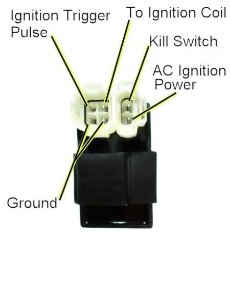
Wire colors are as follows:
2-pin plug
A/C Ign Power: Black w/red stripe
Kill Switch: White w/black stripe
4-pin plug
Ignition trigger Pulse: Blue w/yellow stripe
To Ignition Coil:Black w/yellow stripe
Ground wires (2 of them): one black w/blue stripe and one green
Here are instructions I pulled from another thread regarding no spark on a different type of quad and my test results.
Set your meter to read AC volts on the 200 volt scale. Test your meter by sticking the probes into a wall power outlet in your house. You should see about 120 volts AC. If you get that you know your meter is set up properly and working.
Now disconnect the CDI from the quad wiring harness. Measure the AC voltage on the AC ignition power pin of the wiring harness to engine ground while cranking the starter motor. That will be putting one lead on the wiring harness pin, and the other lead on the aluminum motor block. You should see 45 to 80 volts AC at normal cranking speeds. What do you measure?
A: 95.2 VAC [So your CDI is definately AC powered]
Set your meter to the lowest AC voltage scale that is has. 2 volts AC full scale would be ideal but many meters don't go that low. Use whatever the lowest range is, but make sure it is AC volts and not DC volts. Measure the voltage on the timing trigger pin in the wiring harness to engine ground while cranking the starter. You should see 0.2 to 0.5 volts AC. What do you measure?
Now, I assume this is the ignition trigger pulse, but again, this troubleshooting guide was for a different type CDI (single plug 6 pin)
A: Lowest setting is 200 VAC. Reading was 00.0 VAC [I have meters like that too. 200 volts is really not good enough to measure 0.2 volts but often that is the best available. It is common for these meters to read 00.0 volts even though there is a little voltage present. But that said, 00.0 volts is wrong (assuming your meter is reading correctly - which is not a given...). ]
Set your meter to measure resistance (ohms) on the 2K ohms scale (2000 ohms). When on the resistance settings you should read zero ohms with the leads shorted, and infinite ohms when the leads are not connected together.
Turn off the quad ignition switch. Measure the AC Ignition Power pin on the wiring to engine ground with the engine sitting still (not cranking). You should see 450 ohms or so (0.450 Kohms). Measure the Timing Trigger line to ground. You should read 150 ohms or so (0.150 Kohms) with the engine sitting still. What do you measure for both of those pins?
A: 320 ohms / 149 ohms [Both these look OK]
Set your meter to the lowest resistance scale it has (20 ohms is about right).. Measure the resistance of the ground pin in the CDI to engine ground. It should read zero ohms. Measure the Ignition coil pin to engine ground. It should 0.5 ohms or so. It should not read zero ohms. Report back any discrepancies with these two values.
A: 2 each ground pins (both read 0.1 ohms) / Ign coil to ground 0.5 ohms [Both these look OK]
I am unable to find a wiring diagram for this quad anywhere online. The one I did find wasn't even close, even though it said it was for a Yamoto 250cc. Any guidance as to where I go next?
Thanks,
Roger
I have the pictured CDI type below and all readings are done at it's connectors
Wire colors are as follows:
2-pin plug
A/C Ign Power: Black w/red stripe
Kill Switch: White w/black stripe
4-pin plug
Ignition trigger Pulse: Blue w/yellow stripe
To Ignition Coil:Black w/yellow stripe
Ground wires (2 of them): one black w/blue stripe and one green
Here are instructions I pulled from another thread regarding no spark on a different type of quad and my test results.
Set your meter to read AC volts on the 200 volt scale. Test your meter by sticking the probes into a wall power outlet in your house. You should see about 120 volts AC. If you get that you know your meter is set up properly and working.
Now disconnect the CDI from the quad wiring harness. Measure the AC voltage on the AC ignition power pin of the wiring harness to engine ground while cranking the starter motor. That will be putting one lead on the wiring harness pin, and the other lead on the aluminum motor block. You should see 45 to 80 volts AC at normal cranking speeds. What do you measure?
A: 95.2 VAC [So your CDI is definately AC powered]
Set your meter to the lowest AC voltage scale that is has. 2 volts AC full scale would be ideal but many meters don't go that low. Use whatever the lowest range is, but make sure it is AC volts and not DC volts. Measure the voltage on the timing trigger pin in the wiring harness to engine ground while cranking the starter. You should see 0.2 to 0.5 volts AC. What do you measure?
Now, I assume this is the ignition trigger pulse, but again, this troubleshooting guide was for a different type CDI (single plug 6 pin)
A: Lowest setting is 200 VAC. Reading was 00.0 VAC [I have meters like that too. 200 volts is really not good enough to measure 0.2 volts but often that is the best available. It is common for these meters to read 00.0 volts even though there is a little voltage present. But that said, 00.0 volts is wrong (assuming your meter is reading correctly - which is not a given...). ]
Set your meter to measure resistance (ohms) on the 2K ohms scale (2000 ohms). When on the resistance settings you should read zero ohms with the leads shorted, and infinite ohms when the leads are not connected together.
Turn off the quad ignition switch. Measure the AC Ignition Power pin on the wiring to engine ground with the engine sitting still (not cranking). You should see 450 ohms or so (0.450 Kohms). Measure the Timing Trigger line to ground. You should read 150 ohms or so (0.150 Kohms) with the engine sitting still. What do you measure for both of those pins?
A: 320 ohms / 149 ohms [Both these look OK]
Set your meter to the lowest resistance scale it has (20 ohms is about right).. Measure the resistance of the ground pin in the CDI to engine ground. It should read zero ohms. Measure the Ignition coil pin to engine ground. It should 0.5 ohms or so. It should not read zero ohms. Report back any discrepancies with these two values.
A: 2 each ground pins (both read 0.1 ohms) / Ign coil to ground 0.5 ohms [Both these look OK]
I am unable to find a wiring diagram for this quad anywhere online. The one I did find wasn't even close, even though it said it was for a Yamoto 250cc. Any guidance as to where I go next?
Thanks,
Roger
#5
09-14-2011, 10:45 PM
Electrical Expert
Likes High Voltage In The Tub!
Likes High Voltage In The Tub!
Join Date: Dec 2008
Location: Tracy, California, USA
Posts: 3,260
Likes: 0
Received 12 Likes
on
12 Posts
The messages are showing up in my "visitor messages" and not private messages. I think you have to click on your highlighted name and then poke around in there to see stuff already posted in visitor messages - unless there has been a response in which case you would be notified upon login, in which case you would get a link that takes you directly there....
#6
09-14-2011, 10:58 PM
Electrical Expert
Likes High Voltage In The Tub!
Likes High Voltage In The Tub!
Join Date: Dec 2008
Location: Tracy, California, USA
Posts: 3,260
Likes: 0
Received 12 Likes
on
12 Posts
Lynn, one more thing to note that I forgot to mention. When I turn the ignition on, and the kill switch is turned off (so the 12vdc is at the CDI) With the plug connected on the CDI and with the engine sitting still (not cranking it over) I am also reading 12vdc coming out of the CDI on the AC ignition wire pin? Is that normal?
Roger
Roger
You really have 12 volts at the CDI? On which pins? Is this with the CDI connected, or disconnected? This completely wrong for the CDIs that I'm familiar with, but remember I don't know anything about dual cylinder CDI's
So do you have one ignition coil (with two high tension leads coming out of the same ignition coil), or do you have two ignition coils?
#7
09-14-2011, 11:03 PM
Join Date: Sep 2011
Posts: 124
Likes: 0
Received 0 Likes
on
0 Posts
I bought the CDI from here: Cdi 19 for Chinese Atvs Scooters Dirt Bikes Go Karts - Cd270-19 - Cdi Boxes - Electrical Parts - In
As for shorting it out (I assume because it got really hot and popped my main fuse near the battery) when I cross wired the left side start/light/kill switch assy). Why was I wiring that up you ask? Well, it went bad on me and not a single place online had the correct connector for replacement switch assy's. So since this Yamoto is a clone of a Kawasaki Bayou, I bought a Bayou switch assy and de-pinned the connector and re-pinned it into my old connector off the bad switch assy.
The plug on the old assy was 7 male-pin wires in a 9-pin square plug. Every place I looked for parts all had different plugs and almost all were female pins anyways. The only difference b/w the Bayou and Yamoto assy is the Yamoto was 7 wires while the Bayou was only 6 wires. After some trial and error, I have everything working (kill/start/lights-high, low, off). Initially I did get it to start, but that was as soon as I plugged up the connector (I had two wires incorrect in the plug...lol......). But when I went to fix that, I put a power pin connecting to the green (ground wire) on the quad side and that is when the CDI got really hot and popped the main fuse. Every since then, I have no spark, so replaced the CDI as stated before....and now this is where I am. I hope this all makes since. The only wire on the quad side connector that now has nothing going to it is the green ground wire..........I jumped that to frame ground today just to see if it made any difference with any switch function and it did not.
As for the same looking CDI's for both AC and DC powered, I've checked several sites for parts and the descriptions don't seem to specify that information. So, it may be possible I did buy the wrong CDI and why I am not getting any output the the coil/plugs.
I'll try to see if I can get my hands on a smaller scale AC meter. I have several meters and need to find them all to see if any have that small a scale. The two meters I used today did not go lower than 200vac.
Trending Topics
#8
09-14-2011, 11:17 PM
Join Date: Sep 2011
Posts: 124
Likes: 0
Received 0 Likes
on
0 Posts
I do not understand the "the kill switch is turned off (so the 12vdc is at the CDI)" part. On a normal single cylinder AC powered CDI there is no 12 volt anything connected to the CDI, thus this has me wondering...
You really have 12 volts at the CDI? On which pins? Is this with the CDI connected, or disconnected? This completely wrong for the CDIs that I'm familiar with, but remember I don't know anything about dual cylinder CDI's
So do you have one ignition coil (with two high tension leads coming out of the same ignition coil), or do you have two ignition coils?
So if I understand you correctly, the "kill switch" wire should not have 12 vdc on it at the CDI? Then how does it function? I always thought the kill switch functioned by removing the 12 vdc from the system.....or perhaps it should be wired to remove ground from the system? That could be my problem....Maybe I still don't have the left switch assy quite wired correctly. What do you think?
On another note, I did find a switch assy today that has the correct connector and pins, but does not have the choke lever on it like I need. I ordered it today as the choke is not important at this stage just to check to see if i did in fact wire something wrong. I think that will help me for sure narrow this down........and possibly my old CDI isn't bad after all.
#9
09-15-2011, 03:37 PM
Join Date: Sep 2011
Posts: 124
Likes: 0
Received 0 Likes
on
0 Posts
Lynn,
I did have a meter that would adjust down to 2 VAC and checked the trigger pulse wire.....I do get my .2 VAC when cranking. so all my readings are normal. So, I'm convinced more than ever that when I wired up the new left side switch assy, that somehow the kill circuit is wrong. Further proving my point, I tried starting my other vehicles (2 motorcycles, 3-wheeler, 1 other quad) with the kill switch in the KILL position and the engine still turns over, but doesn't start (as it should). While with this Yamoto, with the kill switch in the KILL position my engine does not turn over when trying to start. As I said, I have a new switch assy coming with the correct plug (found yesterday online) and am going to wait to get that and see what happens. Only problem with this new switch is it does not have the choke lever attachment on the bottom like my old switch. But in any case, I'll be on hold with this thread until I get that switch and will update you to the results.
Thanks again for all your assistance as well as all the great info on the other threads which helped me too.
Roger
#10
09-15-2011, 11:10 PM
Electrical Expert
Likes High Voltage In The Tub!
Likes High Voltage In The Tub!
Join Date: Dec 2008
Location: Tracy, California, USA
Posts: 3,260
Likes: 0
Received 12 Likes
on
12 Posts
I bought the CDI from here: Cdi 19 for Chinese Atvs Scooters Dirt Bikes Go Karts - Cd270-19 - Cdi Boxes - Electrical Parts - In
........As for the same looking CDI's for both AC and DC powered, I've checked several sites for parts and the descriptions don't seem to specify that information. So, it may be possible I did buy the wrong CDI and why I am not getting any output the the coil/plugs......
........As for the same looking CDI's for both AC and DC powered, I've checked several sites for parts and the descriptions don't seem to specify that information. So, it may be possible I did buy the wrong CDI and why I am not getting any output the the coil/plugs......