For the electrically savy.......
#1
 01-13-2010, 05:36 AM


Join Date: Oct 2009
Posts: 16
Likes: 0
Received 0 Likes
on
0 Posts
Okay, I'm back.... I would first like to say thanks for the information that I received to my last question and throughout the forum. I have been mechanically ignorant, but have recently absorbed a tremendous amount of knowledge here.
Problem:
I origninally posted about my bike not running unless chocked, and then it ran roughly. I cleaned my carburator and put it back together as suggested. My bike would not start no matter where the choke was nor with the help of starting fluid. Frustrated, put it on the back burner until today. Purchased a new carb, put it on and still nothing. It will turn over. As I released the ignition button, it would pop weakly (as if the only time it would try to combust). Read several posts here: deducted that I should check for a spark. Actually replaced the spark plug first since it is cheap. Waited for dark, and checked for a spark. The only time the spark plug will fire is when the ignition button is released (after cranking), it will fire one time and one time only- I see the spark. Also put my finger over the whole (with spark plug absent) and good (seems strong to me) vaccum and pressure.
Where do I start with this symptom? Is it most likely a kill switch gone bad? Faulty CDI? Timing? Okay that is as intelligent as I can sound
Thanks again!
#3
01-13-2010, 08:28 AM

KTM Patrol
Former Chinese POW!
Former Chinese POW!
#4
01-13-2010, 10:25 AM

Electrical Expert
Likes High Voltage In The Tub!
Likes High Voltage In The Tub!
Join Date: Dec 2008
Location: Tracy, California, USA
Posts: 3,260
Likes: 0
Received 12 Likes
on
12 Posts
This is now the fourth time I've read about this strange problem.
Twice the problem was fixed by fiddling with the trigger pickup coil mounted outside the flywheel. In one case it was claimed that the problem was fixed by removing rust from the pickup coil and flywheel. I doubt that, but the fact remains that they were messing around in the area of the trigger pickup coil when it started to work. Both of the cases where the problem was resolved were on Gy6 powered buggies.
The third time was on this forum recently. I don't know if it was resolved. Here is a link to that thread:
http://forums.atvconnection.com/kids...-me-crazy.html
As I did in the above link, I'll send you a link to one of two of the buggy posts by private mail. I could only find one of the two threads.
Quite a while ago Mach179GE on this forum traced out his entire V4S wiring diagram. As you can see he did an excellent job. Here it is in case you don't have it:
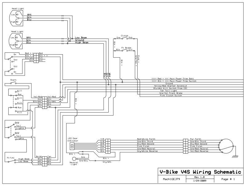
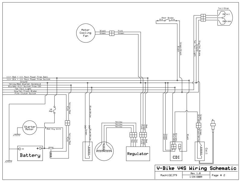
Note that your CDI is powered by 12 volts DC, and not the more common high voltage AC. Also note that on the 6 pin CDIs both the DC and AC units look identical (DC units are often slightly bigger). If you decide to try a new CDI be sure to buy the right one. AC powered CDI's plugged into a DC powered quad go *BANG* when you turn on the ignition switch. This doen't hurt anything but the new (wrong) CDI, which will now have a large extra hole in it.
Also note that the kill switch works by shorting the trigger wire to ground instead of going into the normal CDI kill switch pin.
I would start by unplugging the CDI and measuring the resistance of the trigger winding to ground through the wiring harness (blue-white to green). Kill switch must be in the run position while testing this. Should be 150 ohms or so. Then measure the voltage on this winding while cranking the engine over. You should measure 0.2 to 0.3 volts AC. I would also try to move the trigger pickup coil closer to the flywheel. Caution: There is usually a raised bump on the flywheel that passes under pickup coil. Make sure that clears the pickup coil. On some quads (like etons) this gap between the flywheel bump and pickup is adjustable. Etons have this gap set to 0.025" as a reference point. A smaller gap means higher trigger voltage.
While you're at it measure the power pin to make sure you have 12 volts DC when the igntion is on. Measure the continuity on the ground wires to the engine frame. Measure the ignition output wire resistance through the coil to ground. Should be 1 or 2 ohms.
If you do find the cause of this problem please report back so that it becomes part of the knowledge base to help others with the same problem.
Twice the problem was fixed by fiddling with the trigger pickup coil mounted outside the flywheel. In one case it was claimed that the problem was fixed by removing rust from the pickup coil and flywheel. I doubt that, but the fact remains that they were messing around in the area of the trigger pickup coil when it started to work. Both of the cases where the problem was resolved were on Gy6 powered buggies.
The third time was on this forum recently. I don't know if it was resolved. Here is a link to that thread:
http://forums.atvconnection.com/kids...-me-crazy.html
As I did in the above link, I'll send you a link to one of two of the buggy posts by private mail. I could only find one of the two threads.
Quite a while ago Mach179GE on this forum traced out his entire V4S wiring diagram. As you can see he did an excellent job. Here it is in case you don't have it:
Note that your CDI is powered by 12 volts DC, and not the more common high voltage AC. Also note that on the 6 pin CDIs both the DC and AC units look identical (DC units are often slightly bigger). If you decide to try a new CDI be sure to buy the right one. AC powered CDI's plugged into a DC powered quad go *BANG* when you turn on the ignition switch. This doen't hurt anything but the new (wrong) CDI, which will now have a large extra hole in it.
Also note that the kill switch works by shorting the trigger wire to ground instead of going into the normal CDI kill switch pin.
I would start by unplugging the CDI and measuring the resistance of the trigger winding to ground through the wiring harness (blue-white to green). Kill switch must be in the run position while testing this. Should be 150 ohms or so. Then measure the voltage on this winding while cranking the engine over. You should measure 0.2 to 0.3 volts AC. I would also try to move the trigger pickup coil closer to the flywheel. Caution: There is usually a raised bump on the flywheel that passes under pickup coil. Make sure that clears the pickup coil. On some quads (like etons) this gap between the flywheel bump and pickup is adjustable. Etons have this gap set to 0.025" as a reference point. A smaller gap means higher trigger voltage.
While you're at it measure the power pin to make sure you have 12 volts DC when the igntion is on. Measure the continuity on the ground wires to the engine frame. Measure the ignition output wire resistance through the coil to ground. Should be 1 or 2 ohms.
If you do find the cause of this problem please report back so that it becomes part of the knowledge base to help others with the same problem.
#5
01-19-2010, 03:34 PM
Join Date: Oct 2009
Posts: 16
Likes: 0
Received 0 Likes
on
0 Posts
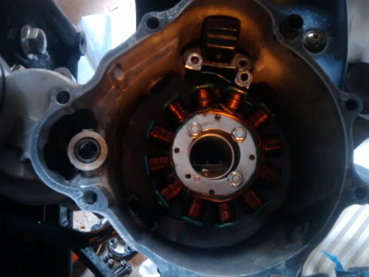
Thanks again for all the help. Update: I pulled the cover off of the flywheel and cleaned the rust off of the flywheel and trigger pick up coil... Just kidding... The trigger pick up coil is what I believe to be the black box with the magnet at the top of the picture correct? If so, do I need to take the black piece apart to adjust the spacing? I otherwise don't readily see a way of doin so. If not, I am thinking of just replacing it.
I was pre-ocupied with figuring out how to tear the bike apart as soon as I got time, and I totally forgot to measure the resistance of anything as you suggested. I will do this when I get everything back in place.
I was pre-ocupied with figuring out how to tear the bike apart as soon as I got time, and I totally forgot to measure the resistance of anything as you suggested. I will do this when I get everything back in place.
#6
01-20-2010, 11:02 PM
Electrical Expert
Likes High Voltage In The Tub!
Likes High Voltage In The Tub!
Join Date: Dec 2008
Location: Tracy, California, USA
Posts: 3,260
Likes: 0
Received 12 Likes
on
12 Posts
The trigger pick up coil is what I believe to be the black box with the magnet at the top of the picture correct? If so, do I need to take the black piece apart to adjust the spacing? I otherwise don't readily see a way of doin so. If not, I am thinking of just replacing it.
Closer (smaller gap) means more trigger voltage. Just be sure that it clears the raised bump on the flywheel. 0.025" is what etons are set at for a ball park figure.
I would definately measure everything else that you can as well. Measuring all this with an oscilloscope would be ideal, but probably not practical in this case. So in the absence of that we need to chew on as much data as we can. We're forging knowledge. Hmmm, that can be interpreted two ways...
#7
08-24-2010, 10:38 PM
Join Date: Oct 2009
Posts: 16
Likes: 0
Received 0 Likes
on
0 Posts
The values I kept getting were very abnormal and then I purchased a new voltometer this past week. These values look much more in line and this is what I got. In the mean time, I did purchase a new CDI unit- but there was no resolution of the problem.
The resistance of the trigger winding to ground through the wiring harness (blue-white to green) was 152.8 Ohm.
The voltage on this winding while cranking the engine over was 2.54 V appears 10x more than expected- it appeared to be true Volts not milivolts or whatever.
The power pin was measured at 12.2 volts DC when the igntion is on.
The continuity on the ground wires to the engine frame was 00.3 Ohm.
The ignition output wire resistance through the coil to ground was 00.6-00.7 Ohm with the key on but not cranking.
I did not see an obvious way of adjusting the distance of the pick up coil on this particular bike. This is not to say I'm not missing something.
I would have given up a long time ago, but there is no repair shop in the area that will work on this bike- so I very much appreciate all of your assistance.
Thanks
Trending Topics
#8
08-25-2010, 12:46 AM
Electrical Expert
Likes High Voltage In The Tub!
Likes High Voltage In The Tub!
Join Date: Dec 2008
Location: Tracy, California, USA
Posts: 3,260
Likes: 0
Received 12 Likes
on
12 Posts
Trigger resistance winding resistance sounds OK.
Ohms to ground on the ground wire sounds OK.
Coil resistance sounds maybe OK. My quad measures higher, at least it is not zero.
Pickup coils are often not adustable (but somtimes they are).
Your trigger voltage is very high compared to most meters (as you reported). But meters are designed to only measure steady state voltages, or at least voltages that change very slowly compared to one second. It is possible that your meter picks the peak voltage on a fast moving waveform, as compared the meters that rectify and then average the results. An oscilloscope is the tool of choice. This is a fancy volt meter that measures fast moving voltages and plots then over time on a graphical display. But we have to work with what we have, which is often not optimum. The peak voltages on the narrow and spikey trigger waveform is plus and minus 5 volts at cranking speeds, but the average voltage is very low at roughly 0.2 to 0.5 volts AC.
So measure the AC voltage at the coil input at cranking using the same meter as before (the one that shows high trigger voltage). What do you see? Once again the voltage here is very narrow spikes. I'm wondering two things: Is your CDI getting triggered, and does you meter read way too high on this spikey waveform too?
#10
08-25-2010, 11:16 PM
Electrical Expert
Likes High Voltage In The Tub!
Likes High Voltage In The Tub!
Join Date: Dec 2008
Location: Tracy, California, USA
Posts: 3,260
Likes: 0
Received 12 Likes
on
12 Posts
The coil input is usually black/yellow - not black/white. Black/white is usually the kill switch wire. Please check that again.
Also, are you sure your meter is able to read to 0.001 volts resolution on an AC voltage scale? That would be unusual unless your meter is very fancy and expensive. What kind of meter is it?
Please measure the AC voltage to the ignition coil again just to be sure we are on the right pin and the meter scale and results are reasonable. What most meters show see is mostly zero readings with occasional high values when the meter happens to capture a voltage spike. I don't know what you meter will do based on the trigger voltage.