panther 100 no spark
#1
 02-10-2013, 12:17 PM


Join Date: Oct 2012
Posts: 12
Likes: 0
Received 0 Likes
on
0 Posts
I have no spark i did the follow test in the forums and at a loss now on what to try.
Method 1) Unplug the CDI and remove the kill switch pin in the CDI connector on the wiring harness. The pin is held in with a spring tab on the pin itself. You'll have to probe into the connector and push this tab in order to extract the pin. Plug the CDI back in (kill switch wire dangling) and see if you have spark. no spark
Method 2) Unplug the CDI. Turn on the ignition switch and set all kill switches to the run position. Use a meter to measure resistance in of the kill switch pin in the wiring harness connector to engine/frame ground. If the resistance is infinite on the 200K ohm scale then your kill switches/kill switch wiring are OK. If you measure zero ohms then you have a kill switch/wiring issue. Working as it should
The other inputs your CDI needs to make spark are AC Ignition Power, and the Trigger signal. Do the following:
1) Unplug the CDI. In the wiring connector measure the resistance of the AC Ignition Power pin to the Ground pin. You should see 400 ohms or so. What do you measure?360 ohms
2) Measure the resistance of the Timing/trigger pin to the ground pin. You should measure 150 ohms or so. What do you measure? 129 ohms
3) Leave the CDI unplugged. Set your meter to measure AC volts on the 100 volt scale. Measure the voltage on the AC Ignition Power pin to the ground pin while cranking the engine. You should see 40 to 80 volts AC while the engine is cranking. What do you measure? 41 volts
4) Set your meter to measure AC volts on the lowest scale you have. Ideally this would be 2 volts but many meters don't go down this low. In that case use the lowest scale you have. Measure the voltage on the Timing Trigger pin to the Ground pin while cranking the engine. You should 0.2 t0 0.4 volts AC. What do you measure? 1.2 volts
Now for measuring the output side of the CDI:
A) Leave the CDI unplugged. In the CDI wiring connector measure the resistance of the Ignition Coil pin to the ground pin. You should measure less than 1 ohm (but not zero ohms). What do you measure? .7 ohms
B) Plug the CDI back in. Set your meter to measure AC volts on the 20 volt scale. Set all kill switches to the run position. Crank the engine while measuring the voltage on the Igntition Coil pin to ground. Poke through the insulation of the wire if you can't probe the connector. .03 volts
#3
02-11-2013, 11:51 PM

Electrical Expert
Likes High Voltage In The Tub!
Likes High Voltage In The Tub!
Join Date: Dec 2008
Location: Tracy, California, USA
Posts: 3,260
Likes: 0
Received 12 Likes
on
12 Posts
This is a puzzler...
All your test responses seem normal except test 4, where you got 1.2 volts for the ignition trigger signal. This is too high, and usually this indicates an open on the trigger wiring to the CDI where the excess voltage measured is actually just stray capacitive coupling from the much higher AC Ignition Power voltage in the wiring harness. But this cannot happen with 129 ohms to ground on the trigger pin. These two measurements are in conflict, with a third caveat of how your meter responds to the very non standard trigger voltage waveform.
I would repeat the trigger voltage tests (AC voltage and resistance to ground) to see if they are still consistent. If you have access to another meter try that too to see if it measures the same.
Then (if you can) try to build this:
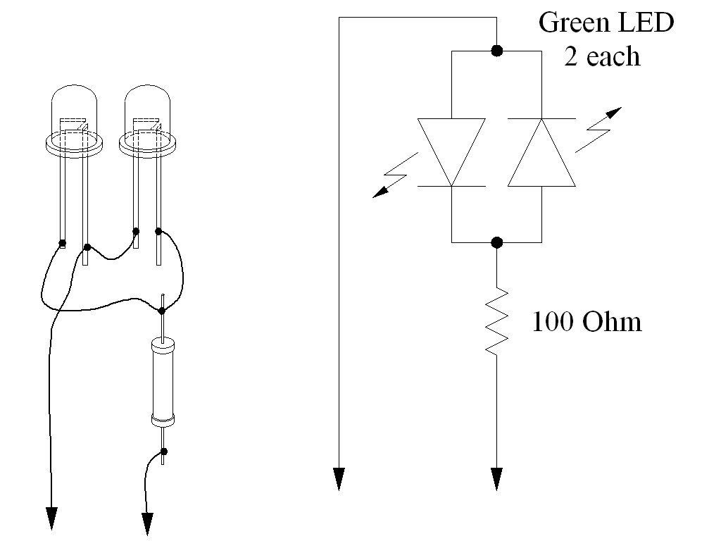
Use this fixture probe the trigger signal (CDI connected or disconnected - it doesn't matter). If while cranking both LEDs flash at about 10 pulses per second while cranking then you've got a good trigger signal. If you don't get this response then you've got trigger problems. All these parts are cheaply available at radio shack.
Your almost zero output voltage to the coil fits the scenario where the CDI is getting power, but is missing a trigger signal.
Above I mentioned that the trigger signal is way non-standard for meters to measure in an absolute predictable way. Meters are not the best tool to use here, but most often it is all that is available. Just for your info here is a graph of what the trigger voltage actually looks like (at cranking speeds):
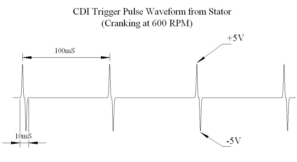
The horizontal axis it time (increasing left to right), and the vertical axis is voltage.
All your test responses seem normal except test 4, where you got 1.2 volts for the ignition trigger signal. This is too high, and usually this indicates an open on the trigger wiring to the CDI where the excess voltage measured is actually just stray capacitive coupling from the much higher AC Ignition Power voltage in the wiring harness. But this cannot happen with 129 ohms to ground on the trigger pin. These two measurements are in conflict, with a third caveat of how your meter responds to the very non standard trigger voltage waveform.
I would repeat the trigger voltage tests (AC voltage and resistance to ground) to see if they are still consistent. If you have access to another meter try that too to see if it measures the same.
Then (if you can) try to build this:
Use this fixture probe the trigger signal (CDI connected or disconnected - it doesn't matter). If while cranking both LEDs flash at about 10 pulses per second while cranking then you've got a good trigger signal. If you don't get this response then you've got trigger problems. All these parts are cheaply available at radio shack.
Your almost zero output voltage to the coil fits the scenario where the CDI is getting power, but is missing a trigger signal.
Above I mentioned that the trigger signal is way non-standard for meters to measure in an absolute predictable way. Meters are not the best tool to use here, but most often it is all that is available. Just for your info here is a graph of what the trigger voltage actually looks like (at cranking speeds):
The horizontal axis it time (increasing left to right), and the vertical axis is voltage.
#6
02-15-2013, 12:27 AM
Electrical Expert
Likes High Voltage In The Tub!
Likes High Voltage In The Tub!
Join Date: Dec 2008
Location: Tracy, California, USA
Posts: 3,260
Likes: 0
Received 12 Likes
on
12 Posts
I should have mentioned that the LED flashing will be dim and will be difficult to see in sunlight. Remember that there is a 10 percent voltage duty cycle. 90% of the time the output voltage is zero. Look for flashing LEDs in the shade, or cup your hands around the LEDs in bright sunlight.
If you really have no flashng LEDs (and you built the fixture correctly) then you have a triggering problem, and that points to the stator or stator wiring. Try moving the LED fixture down to the stator trigger wire and see if it flashes there.
If you really have no flashng LEDs (and you built the fixture correctly) then you have a triggering problem, and that points to the stator or stator wiring. Try moving the LED fixture down to the stator trigger wire and see if it flashes there.
#7
02-15-2013, 08:59 AM
Join Date: Oct 2012
Posts: 12
Likes: 0
Received 0 Likes
on
0 Posts
Trending Topics
 .
.

Thread
Thread Starter
Forum
Replies
Last Post
fordfaithful21
Polaris Ask an Expert! In fond memory of Old Polaris Tech.
9
12-07-2015 05:52 PM
Cdenton
Technical and How-To Articles
1
09-09-2015 11:23 AM
Currently Active Users Viewing This Thread: 1 (0 members and 1 guests)