No Spark On My 150ST-2
#1
 12-21-2012, 02:50 AM


Join Date: Dec 2012
Posts: 2
Likes: 0
Received 0 Likes
on
0 Posts
Hi, i recently inherited at 150ST-2 chinese quad (Unknown Brand...), i have completely rewired it, as the previous owner had destroyed the wiring by joining endless times... anyway, i have wired it up and i can get the starter motor to turn, but no spark...
I also have a 4 wire regulator (yellow, yellow, red, green), i presume the red is (+) battery, green earth, unknown where the 2 yellows go??
I also have a 4 wire regulator (yellow, yellow, red, green), i presume the red is (+) battery, green earth, unknown where the 2 yellows go??
#2
12-21-2012, 02:40 PM

i can tell you that one of those wires is the trigger pulse to the cdi to tell the coil when to fire i also think one of the wires go to the rectifier
LynnEdwards is the electrical guru on the forums he usually gets on late evening my time . He will be able to help you out deffinatly
just have your meter ready
LynnEdwards is the electrical guru on the forums he usually gets on late evening my time . He will be able to help you out deffinatly
just have your meter ready
#3
12-21-2012, 11:42 PM

Electrical Expert
Likes High Voltage In The Tub!
Likes High Voltage In The Tub!
Join Date: Dec 2008
Location: Tracy, California, USA
Posts: 3,260
Likes: 0
Received 12 Likes
on
12 Posts
Hi, i recently inherited at 150ST-2 chinese quad (Unknown Brand...), i have completely rewired it, as the previous owner had destroyed the wiring by joining endless times... anyway, i have wired it up and i can get the starter motor to turn, but no spark...
I also have a 4 wire regulator (yellow, yellow, red, green), i presume the red is (+) battery, green earth, unknown where the 2 yellows go??
I also have a 4 wire regulator (yellow, yellow, red, green), i presume the red is (+) battery, green earth, unknown where the 2 yellows go??
150cc quads ignition systems are usually powerd with a six pin CDI. There are two topologies: DC powered and AC powered. They look identical and are quite different internally. The procedure for testing problem is different between the two as well. So the first step is to see what CDI topology you have. Here is the generic procedure for determining this:
The 2 plug 6 wire CDIs come in two different designs. One is powered off 12 volts DC, and the other is powered off a moderately high voltage AC which comes from the stator. Unfortunately there is no reliable way to tell the difference between the two by just looking at them. To be sure you need to use a meter to find out which you have:
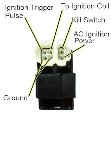
1) Unplug the CDI, and turn on the ignition. Do not crank the starter motor. Use a meter to measure the *DC* voltage on the pin labeled "AC ignition power" in the wiring harness to both ground pins in the 4 pin CDI connector. If you measure 12 volts DC then you have a DC powered CDI.
2) If you don't measure 12 volts DC on the ignition power pin, then switch the meter over to measure AC volts on the 200 volt scale. While cranking the starter motor, measure the AC voltage on the "AC Ignition Power" pin to the the Ground pin. You should see 40 to 80 volts AC. If you measure AC voltage when the starter is turning then you have an AC powered CDI.
Using a meter is the only 100% reliable way to figure out if your CDI is AC or DC powered. But there are some clues you can use that are usually (but not always) correct:
A) DC CDIs tend to be a little larger than their AC powered counterpart. This is because the DC powered CDI needs a bunch more circuitry to convert the 12 volts DC to the moderately high voltage supply that all CDIs must have.
B) Most (but not all) DC powered quad ignition systems do not use the kill switch input pin. The CDI connector pin usually has no wire tied to it. AC powered quad ignition systems usually do use the kill switch input pin.

#5
12-22-2012, 04:53 AM
Join Date: Dec 2012
Posts: 2
Likes: 0
Received 0 Likes
on
0 Posts

#6
12-22-2012, 11:18 AM

Range Rover
Join Date: Apr 2012
Location: only state mentioned it the bible
Posts: 194
Likes: 0
Received 0 Likes
on
0 Posts
#7
12-22-2012, 08:59 PM
Electrical Expert
Likes High Voltage In The Tub!
Likes High Voltage In The Tub!
Join Date: Dec 2008
Location: Tracy, California, USA
Posts: 3,260
Likes: 0
Received 12 Likes
on
12 Posts
Mudmike is correct. The red/blk wire from the stator would be moderately high voltage AC to run the CDI, but since you have a DC powered CDI this wire is not needed.
Here is the generic procedure for troubleshooting a DC powered 6 pin CDI ignition system:
Here is the generic procedure for troubleshooting a DC powered 6 pin CDI ignition system:
To troubleshoot no spark problems on a 6 pin DC powered CDI it makes sense to start in the middle (the CDI), measure as much as we can and branch out from there. For the CDI to do its thing it needs power, a trigger pulse, and it must not be inhibited via the kill switch input pin.
1) Unplug the CDI. Turn the ignition switch on. Set all kill switches the the "run" position. In the wiring harness, look to see if you have a wire on the kill switch pin. If you do, measure the resistance of the kill switch pin to the ground pin on the 20K ohm scale. It should read infinite ohms (same as when the meter leads are hanging free and not touching anything). It should not read zero ohms (shorted).
2) Leave the CDI unplugged. Turn off the ignition switch. Set your meter to the lowest resistance scale you have (like 2 ohms or 20 ohms full scale). Measure the resistance of the "Ignition Coil" pin in the wiring harness to the ground pin. You should read something around 0.7 ohms (but not zero ohms). What do your measure?
3) Leave the CDI unplugged and the ignition switch off. Set your meter to the lowest resistance scale you have (like 2 ohms or 20 ohms full scale). Measure the resistance of the "Ground" pin in the wiring harness to the the negative battery terminal. You should read zero ohms. What do your measure?
4) Leave the CDI unplugged, and turn the ignition switch into the "on" position. Use a meter to measure the DC voltage on the pin labeled "AC ignition power" in the wiring harness to the ground wire on the 20 volt DC scale. You should read battery voltage (12 volts). What do you measure?
5) Leave the CDI unplugged. Use a meter to measure the resistance of the "Ignition Trigger Pulse" pin in the wiring harness to the ground wire on the 2K ohm scale. You should read approximately 150 ohms. What do you measure?
6) Set your meter down to the lowest scale you have for measuring AC volts. 2 volts would be ideal, but some meters don't go that low. In that case use the lowest scale you have. While cranking the engine, measure the voltage on the Ignition Trigger Pulse pin in the wiring harness to the ground pin. You should measure 0.2 to 0.5 volts AC. What do you measure?
7) Now plug the CDI back in. Measure the AC voltage on the Ignition Coil pin to the ground pin using the 200 volt scale. If you have to, use a sewing pin to poke through the wire insulation and then put the meter probe on the sewing pin. But don't hold your fingers on the connection during the next test - there may be high voltage here when the engine is turning. With the ignition on and all kill switches set to the "run" position, crank the starter motor. You should see voltages bouncing around at random values and the meter captures all or part of a spark event. What do you see?

Thread
Thread Starter
Forum
Replies
Last Post
fordfaithful21
Polaris Ask an Expert! In fond memory of Old Polaris Tech.
9
12-07-2015 05:52 PM
Cdenton
Technical and How-To Articles
1
09-09-2015 11:23 AM
Currently Active Users Viewing This Thread: 1 (0 members and 1 guests)

