Kazuma Cougar 250 - still chasing spark - need help!
#1
 10-26-2012, 11:54 AM


Join Date: Sep 2012
Posts: 15
Likes: 0
Received 0 Likes
on
0 Posts
So I've read through LynnEdwards' ignition troubleshooting guide and performed all checks with satisfactory results. I'm using an oscilliscope and can see 400V sine-wave-like input to the CDI from the stator. Check. I can see +/- 1V spikes from the trigger pulse coil. Check. I can see 400V spikes on the ignition coil output from the CDI. Check. All measurements made right at the CDI box to rule out wiring issues. As soon as I connect the ignition coils (X2 as this is a vertical twin) I seem to get 1 spark, then the output from the CDI disappears. Tried a couple different CDI's with same results. Ignition coils measure about 1-2 ohm in the primary, so I don't think they're shorted. The one thing I'm completely unsure of is the plug caps. One was missing and the other was not attached to the coil but I found it in a box of parts that I got with the bike. The one I got had a 5K resistor, so I bought another to match. Is it possible that the 5K plug caps are not correct for this ignition configuration? I'm kind of running out of ideas here... Any help would be appreciated.
#2
10-27-2012, 10:40 AM

Electrical Expert
Likes High Voltage In The Tub!
Likes High Voltage In The Tub!
Join Date: Dec 2008
Location: Tracy, California, USA
Posts: 3,260
Likes: 0
Received 12 Likes
on
12 Posts
When you were measuring the trigger signal and the AC Ignition power, were you measuring this with the CDI hooked up or was the CDI unplugged?
400 volts is way too high for cranking speeds. The most I've ever seen is 90 volts RMS. Since you're using an oscilloscope is this peak voltage, or peak to peak? Even if it is peak to peak, 400V sounds too high.
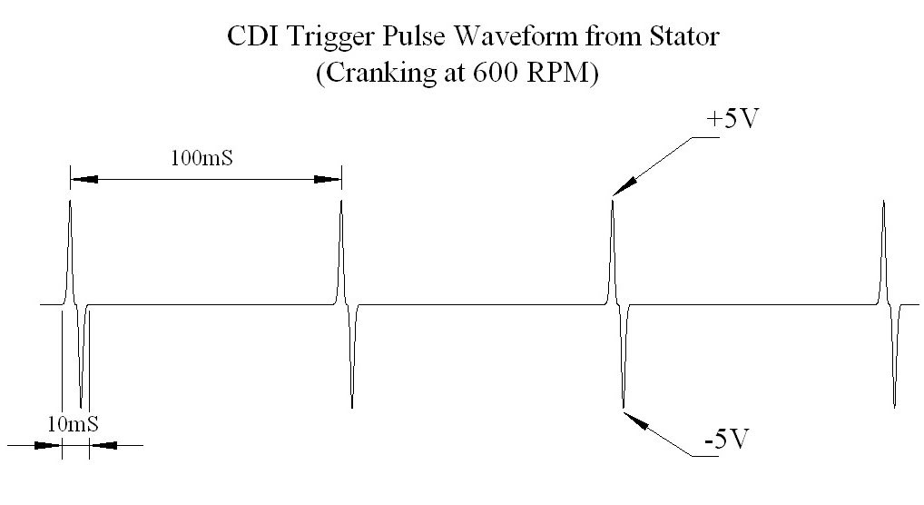
On the other hand, the trigger signal sounds too low. My quad trigger coil puts out +/- 5 volt pulses at cranking speeds. Below I'll post a picture of what my trigger pulses look like.
When you measured the "400V spikes on the ignition coil output from the CDI" am I right in assuming that the ignition coils were disconnected? If so, this won't work. I don't know the internal contruction of your CDI, but so far every one I've taken apart, and everyone that others have posted schematics for, show that the main storage capacitor in the CDI (this capacitor is the "C" in the acronym "CDI") is charged through the resistance of the ignition coil primary. That means that for the CDI to function at all the ignition coils have to be hooked up. On my single output 6 pin CDI if I disconnect the ignition coil I see a mangled version of the AC ignition power waveform trying to charge the main capacitor in the CDI through the ignition coil but this waveform should not be confused with any sort of CDI output. This is what the CDI output should look like:
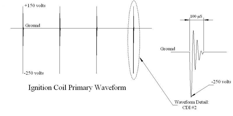
Again this requires that the ignition coils be hooked up.
A "single spark" from the CDI (at the beginning of cranking, or as you let off the start button) is often a symptom of an open trigger wire near the stator. When this happens the long (and open) trigger wire acts as an antenna which picks up transient spike energy from the wiring harness which happens when large currents are switched on and off (i.e. the starter motor). Do you have a kick start? If so see if you *don't* have the single spark when you kick start the quad, and *do* have a single spark when you use the starter motor. If so, I'd look very carefully at the trigger wiring from the stator to the CDI, or the trigger coil itself.
400 volts is way too high for cranking speeds. The most I've ever seen is 90 volts RMS. Since you're using an oscilloscope is this peak voltage, or peak to peak? Even if it is peak to peak, 400V sounds too high.
On the other hand, the trigger signal sounds too low. My quad trigger coil puts out +/- 5 volt pulses at cranking speeds. Below I'll post a picture of what my trigger pulses look like.
When you measured the "400V spikes on the ignition coil output from the CDI" am I right in assuming that the ignition coils were disconnected? If so, this won't work. I don't know the internal contruction of your CDI, but so far every one I've taken apart, and everyone that others have posted schematics for, show that the main storage capacitor in the CDI (this capacitor is the "C" in the acronym "CDI") is charged through the resistance of the ignition coil primary. That means that for the CDI to function at all the ignition coils have to be hooked up. On my single output 6 pin CDI if I disconnect the ignition coil I see a mangled version of the AC ignition power waveform trying to charge the main capacitor in the CDI through the ignition coil but this waveform should not be confused with any sort of CDI output. This is what the CDI output should look like:
Again this requires that the ignition coils be hooked up.
A "single spark" from the CDI (at the beginning of cranking, or as you let off the start button) is often a symptom of an open trigger wire near the stator. When this happens the long (and open) trigger wire acts as an antenna which picks up transient spike energy from the wiring harness which happens when large currents are switched on and off (i.e. the starter motor). Do you have a kick start? If so see if you *don't* have the single spark when you kick start the quad, and *do* have a single spark when you use the starter motor. If so, I'd look very carefully at the trigger wiring from the stator to the CDI, or the trigger coil itself.
#3
10-28-2012, 08:56 PM
Join Date: Sep 2012
Posts: 15
Likes: 0
Received 0 Likes
on
0 Posts
LynnEdwards, thanks for your post. I've taken some pics of the signals I'm getting while cranking. My numbers were a bit off on my previous post, I was going by memory while I didn't have the data in front of me. The CDI disconnected pics suggest to me the stator and trigger coils are OK, but the change in the waveforms when connected seems like something weird happening inside the CDI. As mentioned, I have tried a couple different CDI modules, but am unsure of the state of them ( not new ) Would this info suggest to you a bad CDI?
Thanks


Thanks

#5
10-28-2012, 11:32 PM
Join Date: Sep 2012
Posts: 15
Likes: 0
Received 0 Likes
on
0 Posts
#6
10-31-2012, 09:40 PM
Electrical Expert
Likes High Voltage In The Tub!
Likes High Voltage In The Tub!
Join Date: Dec 2008
Location: Tracy, California, USA
Posts: 3,260
Likes: 0
Received 12 Likes
on
12 Posts
I'm back from the dead partially. This was a nasty flu. I've got a really bad cold now, but otherwise functional. My comments in blue:
WHat about the CDI output waveforms with the ignition coils hooked up?
LynnEdwards, thanks for your post. I've taken some pics of the signals I'm getting while cranking. My numbers were a bit off on my previous post, I was going by memory while I didn't have the data in front of me. The CDI disconnected pics suggest to me the stator and trigger coils are OK, but the change in the waveforms when connected seems like something weird happening inside the CDI. As mentioned, I have tried a couple different CDI modules, but am unsure of the state of them ( not new ) Would this info suggest to you a bad CDI?
Thanks
[The above picture shows a peak to peak waveform (200 Vpp) that roughly matches the meter reading 67.5 volts AC. To do that I take the peak voltage (100 volts) and divide it by the square root of two. That gives 70.7 volts AC, but the formula is only valid for a sine wave, which your waveform clearly isn't. But it is close all around.
Two things puzzle me. First, is why the funny waveshape with the sharp vertical edges rising quickly to the peak voltage. Second, the period of one cycle is roughly 30 mS which is about three times faster than what I would expect from a single AC ignition power coil cranking at 600 RPM - or 10 RPS - or 100 mS per engine revolution. Hmmm. I don't suspect this is your problem, it simply means I don't yet understand what is going on. Perhaps you have multiple AC ignition power windngs...]
[The plus and minus three volt peak trigger signal above looks fine. I notice that the period between trigger signals is roughly 125mS which indicates a cranking speed of 8 RPS, or 480 RPM, which is a little slow compared to my 150cc quad but in the ball park.]
[I see that the ignition power has had all the positive peaks clipped, with only the negative ones remaining. And the AC voltage measured with the meter also is halved which youo would expect. On all the CDIs I've taken apart it is the other way around. The negative excursions are clipped and the positive waveforms pass through. It is possible that the CDI uses a completely different design. It's just a black box that takes in AC power, and a trigger signal, and feeds the CDI with a sharp pulse to fire the plug. There are a zillion ways to do this, I've just never seen this method. ARe you sure you don't have your clip leads going to the 'scope backwards?
Also I see some oscilloscope triggering problems. You don't have a nice steady display as before. I see grayed out waveforms which I assume means the scope is only seeing them intermittently. Does playing with the scope trigger level change the steadiness of the display?]
[The trigger signal level should not change when hooking to the CDI. Of course the signal level will change with engine RPM, but a constant cranking speed the signal level will be constant.
In the above waveform I see a steady (dark) trace, with grayed out spikes in the background which match the amplitude of the trigger signal. Once again I think this is a scope triggering problem. It is synching up on the wrong signal. Play with your trigger level and see if you can get the scope to lock onto the trigger signal from the CDI. If you can do that taht says you are getting a trigger signal.
Also note that your meter is telling you that it is getting roughly the same trigger voltage as before when the CDI was unplugged.]
#7
11-01-2012, 09:52 PM
Electrical Expert
Likes High Voltage In The Tub!
Likes High Voltage In The Tub!
Join Date: Dec 2008
Location: Tracy, California, USA
Posts: 3,260
Likes: 0
Received 12 Likes
on
12 Posts
Two things puzzle me. First, is why the funny waveshape with the sharp vertical edges rising quickly to the peak voltage. Second, the period of one cycle is roughly 30 mS which is about three times faster than what I would expect from a single AC ignition power coil cranking at 600 RPM - or 10 RPS - or 100 mS per engine revolution. Hmmm. I don't suspect this is your problem, it simply means I don't yet understand what is going on. Perhaps you have multiple AC ignition power windngs...]
Trending Topics
#8
11-02-2012, 11:22 AM
Join Date: Sep 2012
Posts: 15
Likes: 0
Received 0 Likes
on
0 Posts
LynnEdwards, good to hear you're back in the land of the living. I've heard its a nasty strain of the flu going around this year.
Here's a little more info;
"[I see that the ignition power has had all the positive peaks clipped, with only the negative ones remaining. And the AC voltage measured with the meter also is halved which youo would expect. On all the CDIs I've taken apart it is the other way around. The negative excursions are clipped and the positive waveforms pass through. It is possible that the CDI uses a completely different design. It's just a black box that takes in AC power, and a trigger signal, and feeds the CDI with a sharp pulse to fire the plug. There are a zillion ways to do this, I've just never seen this method. ARe you sure you don't have your clip leads going to the 'scope backwards?"
I have the ground lead to the chassis and channel 1 to the CDI output.
"Also I see some oscilloscope triggering problems. You don't have a nice steady display as before. I see grayed out waveforms which I assume means the scope is only seeing them intermittently. Does playing with the scope trigger level change the steadiness of the display?"
"In the above waveform I see a steady (dark) trace, with grayed out spikes in the background which match the amplitude of the trigger signal. Once again I think this is a scope triggering problem. It is synching up on the wrong signal. Play with your trigger level and see if you can get the scope to lock onto the trigger signal from the CDI. If you can do that taht says you are getting a trigger signal."
That must be an artifact of the photo, it isn't greyed while viewing it, but the waveform is very noisy. That's the best I could obtain when adjusting trigger level and slope.
"Also note that your meter is telling you that it is getting roughly the same trigger voltage as before when the CDI was unplugged.]
WHat about the CDI output waveforms with the ignition coils hooked up?"
The 'CDI connected' waveforms were measured with the CDI, ignition coils, and spark plugs connected, with the plugs grounded.
As I mentioned in one of my previous posts, I had tried a couple different CDI modules, none of them new, with the same results, suggesting to me that the CDI wasn't the problem. However, I found some cheap $4 GY6 clone CDI modules on eBay, and ordered 3 to play with. I connected a new CDI and all the ignition parts, and was able to get a good strong spark on one plug, but not the other. ( i even widened the gap far too wide to see if there was still enough energy to arc...there was.) So through a process of elimination, substituting plugs, plug caps, plug wires and ignition coils, I determined I have 1 bad ignition coil. The resistance checks are identical for the good one and the bad one, but one sparks quite well, the other not at all. I used to repair TV's years ago and remember that you couldn't test a flyback transformer with a meter, you needed to do a ringing test to check for internally shorted coils that would alter the inductance. I assume an ignition coil would follow the same rules. So, I have new ignition coils on order ( thank goodness for Chinese manufacturers and eBay - $14 for 2 new coils, free shipping from Hong Kong ) Tricky business troubleshooting multiple failures, but I really think I've made some major progress here, and I give you full credit for pointing me in the right direction. My hat is off to you sir, It takes alot of patience to try to help people when most seem to expect you just to diagnose their problems without providing any data. I will repost when the coils arrive and give an update. Thanks again.
#9
11-03-2012, 12:31 AM
Electrical Expert
Likes High Voltage In The Tub!
Likes High Voltage In The Tub!
Join Date: Dec 2008
Location: Tracy, California, USA
Posts: 3,260
Likes: 0
Received 12 Likes
on
12 Posts
My comments in blue:
LynnEdwards, good to hear you're back in the land of the living. I've heard its a nasty strain of the flu going around this year.
Here's a little more info;
"[I see that the ignition power has had all the positive peaks clipped, with only the negative ones remaining. And the AC voltage measured with the meter also is halved which youo would expect. On all the CDIs I've taken apart it is the other way around. The negative excursions are clipped and the positive waveforms pass through. It is possible that the CDI uses a completely different design. It's just a black box that takes in AC power, and a trigger signal, and feeds the CDI with a sharp pulse to fire the plug. There are a zillion ways to do this, I've just never seen this method. ARe you sure you don't have your clip leads going to the 'scope backwards?"
I have the ground lead to the chassis and channel 1 to the CDI output.
"Also I see some oscilloscope triggering problems. You don't have a nice steady display as before. I see grayed out waveforms which I assume means the scope is only seeing them intermittently. Does playing with the scope trigger level change the steadiness of the display?"
"In the above waveform I see a steady (dark) trace, with grayed out spikes in the background which match the amplitude of the trigger signal. Once again I think this is a scope triggering problem. It is synching up on the wrong signal. Play with your trigger level and see if you can get the scope to lock onto the trigger signal from the CDI. If you can do that taht says you are getting a trigger signal."
That must be an artifact of the photo, it isn't greyed while viewing it, but the waveform is very noisy. That's the best I could obtain when adjusting trigger level and slope.
"Also note that your meter is telling you that it is getting roughly the same trigger voltage as before when the CDI was unplugged.]
WHat about the CDI output waveforms with the ignition coils hooked up?"
The 'CDI connected' waveforms were measured with the CDI, ignition coils, and spark plugs connected, with the plugs grounded.
As I mentioned in one of my previous posts, I had tried a couple different CDI modules, none of them new, with the same results, suggesting to me that the CDI wasn't the problem. However, I found some cheap $4 GY6 clone CDI modules on eBay, and ordered 3 to play with. [Uh Oh. Gy6 engines are single cylinder, and a GY6 engine CDI will not drive a dual ignition coil setup. If I recall correctly they may drive one of two coils, leaving the other dead in the water. I'll do some searching...]
I connected a new CDI and all the ignition parts, and was able to get a good strong spark on one plug, but not the other. ( i even widened the gap far too wide to see if there was still enough energy to arc...there was.) So through a process of elimination, substituting plugs, plug caps, plug wires and ignition coils, I determined I have 1 bad ignition coil. The resistance checks are identical for the good one and the bad one, but one sparks quite well, the other not at all. I used to repair TV's years ago and remember that you couldn't test a flyback transformer with a meter, you needed to do a ringing test to check for internally shorted coils that would alter the inductance. I assume an ignition coil would follow the same rules. [Absolutely true. A shorted turn in the secondary winding won't affect the resistance at all, but will drive the inductance to near zero - killing the spark.]
So, I have new ignition coils on order ( thank goodness for Chinese manufacturers and eBay - $14 for 2 new coils, free shipping from Hong Kong ) [Uh Oh. Customs.... I've ordered a lot of stuff from asia. Sometimes it sails through customs, and sometimes it gets held up for weeks. I've had stuff arrive within a week, the longest was six weeks, and others arrived everywhere in between.]
Tricky business troubleshooting multiple failures, but I really think I've made some major progress here, and I give you full credit for pointing me in the right direction. My hat is off to you sir, It takes alot of patience to try to help people when most seem to expect you just to diagnose their problems without providing any data. I will repost when the coils arrive and give an update. Thanks again.
[Please do give an update. It certainly looks like your CDIs were bad since you have spark in one coil now. But I worry that you're out of the frying pan and into the fire using a GY6 style CDI. Let me see if I can find the relevant thread(s).]
#10
11-03-2012, 12:42 AM
Electrical Expert
Likes High Voltage In The Tub!
Likes High Voltage In The Tub!
Join Date: Dec 2008
Location: Tracy, California, USA
Posts: 3,260
Likes: 0
Received 12 Likes
on
12 Posts
Check out this thread:
http://forums.atvconnection.com/chin...-dinosaur.html
And this one:
http://forums.atvconnection.com/chin...ion-issue.html
Let's see if this sheds any light on the problem...
http://forums.atvconnection.com/chin...-dinosaur.html
And this one:
http://forums.atvconnection.com/chin...ion-issue.html
Let's see if this sheds any light on the problem...