Chinese 110 ATV no spark - stator issue?
#1
 03-23-2012, 07:39 PM


Join Date: Mar 2012
Posts: 2
Likes: 0
Received 0 Likes
on
0 Posts
I am very appreciative of the info and insight you share with others!!!
I have a Chinese 110 cc 1 1/2 yr old unit that ran fine and now has no spark. Changed the CDI and coil - nothing....
I have tried unplugging the kill switch wire in the CDI and no luck.

Based on information on the site: I took voltage readings at the CDI (5 pin) harness and have 0V powered on & 61 V cranking at ignition power pin, but NO Volts at ignition trigger while cranking; nor at the kill switch cranking with the CDI plugged in.
I do have another running 110cc ATV that I also took readings on (to make sure I was getting presumably accurate measurements) and got: 57 V cranking at ignition and 0.2 V at trigger cranking and all sorts of readings with the CDI plugged in.
Resistance readings on non running quad: 121 ohms @AC ignition power and 351 ohms at trigger pulse.
Resistance on running quad 152 ohms @ AC ignition and 367 at trigger pulse. Infinite ohms on both at the kill switch.
Would the lack of voltage at the ignition trigger indicate that this is an issue with the stator??
I have read that it is almost always a kill switch, wire, CDI, followed by coil and lastly the stator that tend to fail. The Stator is different on the 2 quads so I cannot try swapping those
Any thoughts or comments would be much appreciated!!!
I have a Chinese 110 cc 1 1/2 yr old unit that ran fine and now has no spark. Changed the CDI and coil - nothing....
I have tried unplugging the kill switch wire in the CDI and no luck.
Based on information on the site: I took voltage readings at the CDI (5 pin) harness and have 0V powered on & 61 V cranking at ignition power pin, but NO Volts at ignition trigger while cranking; nor at the kill switch cranking with the CDI plugged in.
I do have another running 110cc ATV that I also took readings on (to make sure I was getting presumably accurate measurements) and got: 57 V cranking at ignition and 0.2 V at trigger cranking and all sorts of readings with the CDI plugged in.
Resistance readings on non running quad: 121 ohms @AC ignition power and 351 ohms at trigger pulse.
Resistance on running quad 152 ohms @ AC ignition and 367 at trigger pulse. Infinite ohms on both at the kill switch.
Would the lack of voltage at the ignition trigger indicate that this is an issue with the stator??
I have read that it is almost always a kill switch, wire, CDI, followed by coil and lastly the stator that tend to fail. The Stator is different on the 2 quads so I cannot try swapping those
Any thoughts or comments would be much appreciated!!!
#2
03-23-2012, 11:46 PM

Electrical Expert
Likes High Voltage In The Tub!
Likes High Voltage In The Tub!
Join Date: Dec 2008
Location: Tracy, California, USA
Posts: 3,260
Likes: 0
Received 12 Likes
on
12 Posts
It is very fortunate that you have two quads with the same style CDI to measure. Measuring voltages to and from the CDI are best done with an oscilloscope, but that is beyond the reach of most people. Meters are the next best alternative, but they have some major limitations. But we have to do the best with what we have at our disposal.
One of the issues is how well your meter measures the very non-standard trigger pulse waveform. There is always the question of whether the meter is messing up, or the trigger pulse is missing. By measuring two quads you are proving the ability of your meter to measure correctly. That is a big step.
I'm concerned about your report that you don't measure any voltage on the kill switch pin of the CDI while it is hooked up. This is wrong for any CDI I've seen. The kill switch pin voltage is usually the unfiltered half wave rectified AC Ignition Power pin voltage. You read 60 volts or so (unloaded) on the AC Ignition power pin, so you should see big voltages on the kill switch pin too. Please check that again because it makes no sense... But keep in mind that you must have all kill switches set to the run position when you do this test. If any kill switch is on then the kill switch is shorted to ground and you will measure zero volts on the kill switch pin.
I didn't see that you have switched CDIs between the working and non-working quads... Have you tried this?
Your resistance of the ignition trigger and ignition power pins sounds reasonable. Your ignition trigger voltage of zero volts is a red flag. It is unusual for the resistance of the trigger winding to be normal, and then the trigger output to be zero. It can happen, though it is rare. Three scenarios (but again each very unlikely) come to mind:
1) There is a shorted turn in the trigger voltage pickup coil: That shorted turn will not affect the resistance measurement in any appreciable way, but it will destroy the inductance of the pickup coil and produce no output. There is nothing that can be done about that except replace the stator.
2) The pickup coil is spaced too far out from the flywheel: The trigger pickup coil works by having a raised steel bump on the flywheel travel past the pick up coil outside the flywheel in very close proximity. There is a magnet inside the pickup coil that has its magnetic field "disturbed" by the close flyby, and this disturbance wiggles a the magnetic field on the pick up coil and produces an AC voltage. The magnetic field from the embedded magnet in the pickup is bottled up by steel shielding around it's perimeter so that it's externally projected field does not go very far from the open end facing the flywheel. It has to be able to see the raised bump, but it must *not* see the *huge* magnets inside the flywheel that power the AC ignition power and the battery charge windings just fraction of an inch further away. Those magnets are *much* larger than the pickup coil embedded magnet, so it is an engineering challenge to separate these two influences. Hence the "critical" gap between the pickup coil and that raised bump on the flywheel gap. Rule of thumb is that it should be 0.025" You should look at this...
3) The inards of the stator can get messy. Rust and magnetic debris gets thrown around and is attracted to magnets. The pickup coil is most vulnerable to magnetic debris. As it is attracted to and piles up on the trigger coil hot end (facing the flywheel) it further bottles up the output range of the pickup magnet. This is the same thing as moving the trigger coil further away (bad). Look at the trigger pickup coil and make sure it doesn't have an accumulation of magnetic stuff stuck at the face facing the flywheel.
I'm on the fringe here. These are all very rare situations, but also very possible. I would concentrate on repeating the more generic tests again (and maybe a third time too) and make sure they are all repeatable before concentrating on these very unlikely scenarios.
#3
03-25-2012, 12:39 AM
Join Date: Mar 2012
Posts: 2
Likes: 0
Received 0 Likes
on
0 Posts
Lynn. Many Many Thanks! Your knowledge and insight is impeccable!!
Yes, I have tried swappi9ng the CDI's w/ no change.
Early this morning I opened up the kill switch housing on the handlebars and cleaned and retightened the each of the connections... Maybe that helped as I remeasured the non-running quad and got 54.3 VAC cranking at the kill wire w/ the CDI plugged in. (I also remeasured the running quad - w/ the spark plug wire off [to keep it from starting] and got 52.8 V cranking). That is good news, right?
After reading your response, I also remeasured the AC ignition = 57.1V and trigger readings= 0V. Running quad: ignition 58V / trigger 0.2. Thus all readings stayed relatively consistent
Not sure if this helps, but I also took readings from the actual stator wiring and yielded: Yellow wire 0.9 ohms; White 1.0 ohms; blu and white 121 (same color wire as trigger pulse at CDI); and black and red 353 (same wire as AC ignition power)
AND Yellow wire = 3.1 V cranking; White 4.0 cranking; Blu/white 0 V cranking; blk/r 59.4 cranking.
Lastly, I looked at the stator and did not notice anything that looked abnormal � but I would be the first to tell you that I probably would be able to tell. It is noteworthy that sometime shortly before the quad quit, one of the little threaded stator covers must have vibrated out � so it is entirely possible that some debris could have gotten in there.
Would this confirmed data lead you to think it is the stator?
#5
04-06-2012, 07:57 AM

I am trying to fix a buddies sons little chinese 110 which has no spark. They wanted it fixed for his bday but I dont think were going to make it. I did the meter reading tests at the 5 pin CDI like I have seen posted on this site. First test I am supposed to have 45-80 VAC, and I have 35. Next I am supposed to have .2 -.5 and I have 0. Next I am supposed to have 450 ohms and I only have 330. Next I am supposed to have 150 ohms and I have 0. Next I am supposed to have 0 ohms and I have .4, and last but not least I am supposed to have .5 ohms and I do. Please help. If at all possible could you send info to my email,
Decoy-racing@hotmail.com. Thanks in advance
Decoy-racing@hotmail.com. Thanks in advance
#6
04-06-2012, 09:42 PM
Electrical Expert
Likes High Voltage In The Tub!
Likes High Voltage In The Tub!
Join Date: Dec 2008
Location: Tracy, California, USA
Posts: 3,260
Likes: 0
Received 12 Likes
on
12 Posts
My comments embedded inside yours in blue...
I am trying to fix a buddies sons little chinese 110 which has no spark. They wanted it fixed for his bday but I dont think were going to make it. I did the meter reading tests at the 5 pin CDI like I have seen posted on this site. First test I am supposed to have 45-80 VAC, and I have 35.
[I assume this is the AC Ignition Power. 35 volts AC is a little low but you're not complaining about weak spark. You would still get a spark at 35 volts AC.]
Next I am supposed to have .2 -.5 and I have 0.
[I assume this is the Timing/Trigger signal? And you're measuring AC volts on the lowest scale you have (like 2 volts full scale)? Zero volts is a wrong answer.]
Next I am supposed to have 450 ohms and I only have 330.
[It would really help a lot if you would post what it is you're trying to measure instead of us having to guess. I assume this is the resistance of the AC Ignition Power pin? Measured in ohms? If so this may be OK. All stators work on the same general principles, but individual stator designs from model to model can vary. The fact that you have resistance (i.e. it isn't open or shorted), and you have AC voltage being generated is a good sign.]
Next I am supposed to have 150 ohms and I have 0.
[Again, what are you measuring? The timing trigger signal pin? Is this resistance in ohm? Assuming I'm guessing correctly then this is plain wrong, and this is where we need to focus. If my guesses are correct then you have zero volts on the trigger signal wire, and the resistance of this wire to ground is zero. Both are wrong, and therefore this is a big red flag. But I'm guessing. Please verify that my assumptions about what you are measuring are correct. Then we can dig in deeper if you can verify my assumptions...]
Next I am supposed to have 0 ohms and I have .4
[You got me here... What wire exactly are you measuring?]
, and last but not least I am supposed to have .5 ohms and I do
[But what are you measuring? What wire? ]
. Please help. If at all possible could you send info to my email,
Decoy-racing@hotmail.com
[Just so you know, this is considered really bad etiquette on any forum. It is often taken as "I'm too lazy to come back to this group and see if there are any answers, so just send me the answers directly...". The idea of a forum is to publicly exchange problems, ideas, and solutions so that everybody benefits, and contributes to a growing public knowledge base.].
Thanks in advance
#7
04-07-2012, 07:22 AM
Sorry for being so brief, my last post was my third with no responsee and I cant even find where they went which is why I wanted a email sent. The measurements that I believed I was supposed to have came from another area of this site that I cannot find now. Tell me exactly how to test the system the way that you want and I will get the answers back to you.
(My measurements were with engine cranking, ignition power pin to engine ground which I got 35 VAC, timing trigger to the engine groundwhile cranking I got 0 VAC, net I measured in OHMS (2000 scale as directed) Ignition power pin to engine ground in which I got 330 ohms, and the timing trigger to the engine ground I got 0 OHMS. Next I reset the meter to the 200 OHMS setting and measured the ground pin to the engine ground where I found .4 OHMS, and ignition coil pin to engine ground I found .5 OHMS) None of that matters I guess if you cant read it so Give me the step by step and we will do it your way. Thanks again
(My measurements were with engine cranking, ignition power pin to engine ground which I got 35 VAC, timing trigger to the engine groundwhile cranking I got 0 VAC, net I measured in OHMS (2000 scale as directed) Ignition power pin to engine ground in which I got 330 ohms, and the timing trigger to the engine ground I got 0 OHMS. Next I reset the meter to the 200 OHMS setting and measured the ground pin to the engine ground where I found .4 OHMS, and ignition coil pin to engine ground I found .5 OHMS) None of that matters I guess if you cant read it so Give me the step by step and we will do it your way. Thanks again
Trending Topics
#8
04-07-2012, 09:59 AM
Electrical Expert
Likes High Voltage In The Tub!
Likes High Voltage In The Tub!
Join Date: Dec 2008
Location: Tracy, California, USA
Posts: 3,260
Likes: 0
Received 12 Likes
on
12 Posts
Sorry for being so brief, my last post was my third with no responsee and I cant even find where they went which is why I wanted a email sent. The measurements that I believed I was supposed to have came from another area of this site that I cannot find now. Tell me exactly how to test the system the way that you want and I will get the answers back to you.
(My measurements were with engine cranking, ignition power pin to engine ground which I got 35 VAC, timing trigger to the engine groundwhile cranking I got 0 VAC, net I measured in OHMS (2000 scale as directed) Ignition power pin to engine ground in which I got 330 ohms, and the timing trigger to the engine ground I got 0 OHMS. Next I reset the meter to the 200 OHMS setting and measured the ground pin to the engine ground where I found .4 OHMS, and ignition coil pin to engine ground I found .5 OHMS) None of that matters I guess if you cant read it so Give me the step by step and we will do it your way. Thanks again
(My measurements were with engine cranking, ignition power pin to engine ground which I got 35 VAC, timing trigger to the engine groundwhile cranking I got 0 VAC, net I measured in OHMS (2000 scale as directed) Ignition power pin to engine ground in which I got 330 ohms, and the timing trigger to the engine ground I got 0 OHMS. Next I reset the meter to the 200 OHMS setting and measured the ground pin to the engine ground where I found .4 OHMS, and ignition coil pin to engine ground I found .5 OHMS) None of that matters I guess if you cant read it so Give me the step by step and we will do it your way. Thanks again
Is this a picture of your CDI?
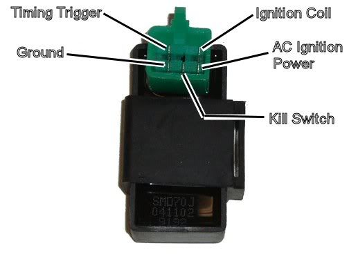
Assuming the answer is yes, the first thing to do is eliminate all kill switches and kill switch wiring:
Method 1) Unplug the CDI and remove the kill switch pin in the CDI connector on the wiring harness. The pin is held in with a spring tab on the pin itself. You'll have to probe into the connector and push this tab in order to extract the pin. Plug the CDI back in (kill switch wire dangling) and see if you have spark.
Method 2) Unplug the CDI. Turn on the ignition switch and set all kill switches to the run position. Use a meter to measure resistance in of the kill switch pin in the wiring harness connector to engine/frame ground. If the reistance is infinite on the 100K ohm scale then your kill switches/kill switch wiring are OK. If you measure zero ohms then you have a kill switch/wiring issue.
The other inputs your CDI needs to make spark are AC Ignition Power, and the Trigger signal. Do the following:
1) Unplug the CDI. In the wiring connector measure the resistance of the AC Ignition Power pin to the Ground pin. You should see 400 ohms or so. What do you measure?
2) Measure the resistance of the Timing/trigger pin to the ground pin. You should measure 150 ohms or so. What do you measure?
3) Leave the CDI unplugged. Set your meter to measure AC volts on the 100 volt scale. Measure the voltage on the AC Ignition Power pin to the ground pin while cranking the engine. You should see 40 to 80 volts AC while the engine is cranking. What do you measure?
4) Set your meter to measure AC volts on the lowest scale you have. Ideally this would be 2 volts but many meters don't go down this low. In that case use the lowest scale you have. Measure the voltage on the Timing Trigger pin to the Ground pin while cranking the engine. You should 0.2 t0 0.4 volts AC. What do you measure?
Now for measuring the output side of the CDI:
A) Leave the CDI unplugged. In the CDI wiring connector measure the resistance of the Ignition Coil pin to the ground pin. You should measure less than 1 ohm (but not zero ohms). What do you measure?
B) Plug the CDI back in. Set your meter to measure AC volts on the 20 volt scale. Set all kill switches to the run position. Crank the engine while measuring the voltage on the Igntition Coil pin to ground. Poke through the insulation of the wire if you can't probe the connector.
Caution: There should be moderately high voltage spikes on this wire. Make sure your fingers are not part of the circuitry. Don't touch the probe lead tips while doing this test.
What you should see is a lot of random numbers with lots of zero values as well. This is because the meter may catch all or part of the spark event voltage, with a lot of nothing in between. Describe what you see.
Note: Using a meter to measure this point produces highly variable results depending on the meter. What you really need is an oscilloscope, but most always a meter is all that is available. We have to do the best we can with what's available. Describe the meter results as accurately as you can - there is information there to chew on....
Look at the color of the wire in the wiring harness fro the timing trigger pin at the CDI connector. Now go down to the stator area where the stator wires emerge from the engine cover. Follow the pigtail wires up to a connector(s) where they connect into the wiring harness. Find the same color wire noted above in the main harness (this is still the timing trigger wire) and note which wire it connects to in the stator pigtail wires. Unplug the stator from the wiring harness and measure the resistance of that wire to ground looking into the stator. If it is zero ohms here then your stator is bad. If it reads 150 ohms (or so) then we got to look further into the wiring harness. Sometimes quads have a kill switch that shorts the trigger line to ground, or maybe you just have a frayed or pinched wire somewhere. But the first step is to see if the short is in the wiring harness or in the stator...
The following users liked this post:
Hillman2 (08-28-2023)
#9
04-09-2012, 12:17 PM
Ok, I am just out of the garage with the test answers.
Method 1, I unplugged the kill switch wire at the CDI and still no spark
Method 2, My scale for Ohms only goes as low as 200k so I probed the kill switch wire and a engine ground resulting in 0.60 ohms.
1. My ohm meter setting goes from 200-2000 so I set it to 2000 and measured the ac ignition power pin and the ground pin resulting in 337 ohms
2. measuring the timing trigger pin to the ground pin my scale did not change.
3. With my meter set to 200 volts AC (low as it goes) I probed the AC ignition power pin and the ground pin while cranking which gave me a reading of 47.2 VAC
4. On a 200 volt AC scale (low as it goes) I probed the timing trigger pin to the ground pin. The result was 0 until I let off the starter button then numbers came up but quickly returned to zero. It dont matter if the kill switch is on or off, plugged in or not.
A. Setting the meter back to 200 ohms I probed the ignition coil pin and the ground pin resulting in 0.5 ohms
B. With the CDI plugged back in I set the meter to 200 VAC (low as it goes), I set the kill switch to run, and back probed the ignition pin and a engine ground resulting in no movement on the scale until I let off the starter button then numbers came up but quickly returning to zero. It dont matter if the kill switch is on or off, plugged in or not.
The last test was your BRF(big red flag). I set my meter to the 200 ohm setting. I traced the timing trigger wire to the engine housing where I probled the wire and a engine ground which resulted in no movement in the meter.
I ran through all of these tests 3 times to make sure I didnt make a mistake and had the same result each time. Hopefully the answers lead to a diagnosis. Thanks again for the help
#10
04-10-2012, 12:29 AM
Electrical Expert
Likes High Voltage In The Tub!
Likes High Voltage In The Tub!
Join Date: Dec 2008
Location: Tracy, California, USA
Posts: 3,260
Likes: 0
Received 12 Likes
on
12 Posts
My comments embedded in blue...
If I'm deciphering your data correctly I think we are looking at an open trigger coil in the stator, but the answers above will hopefully clarify that somewhat. There is also an issue with the kill switch pin measurements since you are measuring resistances that are not open. But disconnecting the kill switch wire to the CDI did not cause spark to return, so this is a secondary problem. Let's attack this on two fronts by doing all the measurements and see where this leads.
Ok, I am just out of the garage with the test answers.
Method 1, I unplugged the kill switch wire at the CDI and still no spark
Method 2, My scale for Ohms only goes as low as 200k so I probed the kill switch wire and a engine ground resulting in 0.60 ohms. [Uh-Oh this is very wrong. First your ohms scale has to go lower than 200K. In the very next step (#1 - immediately below) you said it goes to 200 ohms. There is a huge difference between 200 ohms and 200K ohms. If you looked at your bank statement and saw you had 200 dollars instead of 200 thousand dollars (200 bucks versus 200K bucks), I think you'd agree with me that this is a huge difference Either way (200K ohm setting or 200 ohms setting) this is a wrong reading. Please do this test again and make absolutely sure all kill switches are in the "run" condition (tether pull cord, handlebar kill/run switch, and the ignition switch is on) when you do this test. And do it on both scales (200 ohm and 200K ohms) just to see what you get]
1. My ohm meter setting goes from 200-2000 so I set it to 2000 and measured the ac ignition power pin and the ground pin resulting in 337 ohms [OK]
2. measuring the timing trigger pin to the ground pin my scale did not change. [Meaning that it measured the same as with the meter leads disconnected? Or does it measure the same as when the meter leads are shorted? You're measuring resistance. What I'm asking is whether you are measure an open circuit (same as when the meter leads are not connected), or are you measuring a shorted circuit (same as when the meter leads are shorted together). Both of these are wrong. But the difference between the two scenarios is really important]
3. With my meter set to 200 volts AC (low as it goes) I probed the AC ignition power pin and the ground pin while cranking which gave me a reading of 47.2 VAC [OK]
4. On a 200 volt AC scale (low as it goes) I probed the timing trigger pin to the ground pin. The result was 0 until I let off the starter button then numbers came up but quickly returned to zero. It dont matter if the kill switch is on or off, plugged in or not. [This is wrong, but the single burst of voltage when you let off the starter button points to an open timing trigger coil, which maybe agrees with the symptoms in answer #2 above - based on your further input as requested above.]
A. Setting the meter back to 200 ohms I probed the ignition coil pin and the ground pin resulting in 0.5 ohms [OK]
B. With the CDI plugged back in I set the meter to 200 VAC (low as it goes), I set the kill switch to run, and back probed the ignition pin and a engine ground resulting in no movement on the scale until I let off the starter button then numbers came up but quickly returning to zero. It dont matter if the kill switch is on or off, plugged in or not. [Again this is sounding like an open trigger coil (either in the stator or in the wiring).]
The last test was your BRF(big red flag). I set my meter to the 200 ohm setting. I traced the timing trigger wire to the engine housing where I probled the wire and a engine ground which resulted in no movement in the meter. [Open or shorted (as per #2 comments above)? It's a huge difference and really important.]
I ran through all of these tests 3 times to make sure I didnt make a mistake and had the same result each time. Hopefully the answers lead to a diagnosis. Thanks again for the help
Method 1, I unplugged the kill switch wire at the CDI and still no spark
Method 2, My scale for Ohms only goes as low as 200k so I probed the kill switch wire and a engine ground resulting in 0.60 ohms. [Uh-Oh this is very wrong. First your ohms scale has to go lower than 200K. In the very next step (#1 - immediately below) you said it goes to 200 ohms. There is a huge difference between 200 ohms and 200K ohms. If you looked at your bank statement and saw you had 200 dollars instead of 200 thousand dollars (200 bucks versus 200K bucks), I think you'd agree with me that this is a huge difference
Either way (200K ohm setting or 200 ohms setting) this is a wrong reading. Please do this test again and make absolutely sure all kill switches are in the "run" condition (tether pull cord, handlebar kill/run switch, and the ignition switch is on) when you do this test. And do it on both scales (200 ohm and 200K ohms) just to see what you get]1. My ohm meter setting goes from 200-2000 so I set it to 2000 and measured the ac ignition power pin and the ground pin resulting in 337 ohms [OK]
2. measuring the timing trigger pin to the ground pin my scale did not change. [Meaning that it measured the same as with the meter leads disconnected? Or does it measure the same as when the meter leads are shorted? You're measuring resistance. What I'm asking is whether you are measure an open circuit (same as when the meter leads are not connected), or are you measuring a shorted circuit (same as when the meter leads are shorted together). Both of these are wrong. But the difference between the two scenarios is really important]
3. With my meter set to 200 volts AC (low as it goes) I probed the AC ignition power pin and the ground pin while cranking which gave me a reading of 47.2 VAC [OK]
4. On a 200 volt AC scale (low as it goes) I probed the timing trigger pin to the ground pin. The result was 0 until I let off the starter button then numbers came up but quickly returned to zero. It dont matter if the kill switch is on or off, plugged in or not. [This is wrong, but the single burst of voltage when you let off the starter button points to an open timing trigger coil, which maybe agrees with the symptoms in answer #2 above - based on your further input as requested above.]
A. Setting the meter back to 200 ohms I probed the ignition coil pin and the ground pin resulting in 0.5 ohms [OK]
B. With the CDI plugged back in I set the meter to 200 VAC (low as it goes), I set the kill switch to run, and back probed the ignition pin and a engine ground resulting in no movement on the scale until I let off the starter button then numbers came up but quickly returning to zero. It dont matter if the kill switch is on or off, plugged in or not. [Again this is sounding like an open trigger coil (either in the stator or in the wiring).]
The last test was your BRF(big red flag). I set my meter to the 200 ohm setting. I traced the timing trigger wire to the engine housing where I probled the wire and a engine ground which resulted in no movement in the meter. [Open or shorted (as per #2 comments above)? It's a huge difference and really important.]
I ran through all of these tests 3 times to make sure I didnt make a mistake and had the same result each time. Hopefully the answers lead to a diagnosis. Thanks again for the help

