I Need Help Rewiring My 110!
#1
 05-18-2011, 10:21 PM


Join Date: May 2011
Posts: 2
Likes: 0
Received 0 Likes
on
0 Posts
On the plate over the rear left tire says that this is a XIONGTAI
displacement: 107cc
engine family: 7XNGX.125AM3
i got this quad the other day and the wiring is a mess. i've rewired one of these before so i know the basics. This one had the remote start on it but i dont have that box so i'm hoping i can just bypass it. there are no lights anymore(they were removed). it has front and rear brakes but they are disconnected and i don't know where they hook up at. so i'm just going to list what i have now and see if anyone has any input.
Coming from the motor (Magneto) i have 5 wires, Green, Yellow, White, which go to the rectifier, and Blue/White, Red/Black, which go to the 5 pin CDI. those are the only 2 wires that are connected to anything from the cdi, but there are three more wires coming out of the cdi i'm just not sure where they go to. there is a Green, which i think is ground, a Black/White, and a Yellow/Black which i think is supposed to hook to the coil.
From my solenoid i have a heavy gauge Red wire on one pole that goes to the starter and on the other pole there are two wires, one heavy gauge red wire which i think would go to battery positive and a little red wire that is hooked up to the rectifier. i'm not sure if this is right. there are two wires coming out of the middle of the solenoid, a Red/Yellow and a Green/Yellow. i'm not sure if they are hooked up right but i have the Green/Yellow grounded and the Red/yellow hooked to a push button switch and then to the battery. there is a front brake that has two wires coming from it, a Black and a Yellow/Green. they are not connected to anything . the foot brake also has two wires, same color as the front and it isn't hooked up to anything.
Right now the motor turns over i just don't have spark, and i'm thinkin its just because i don't have everything connected right..
Now that I've got everything down maybe you guys could help me from here. any advice would be appreciated. I've been looking at diagrams all day and it's hard because i don't have lights and stuff anymore. i've got a test light and ohmmeter to use. so any help would be awesome because this little things drivin me crazy!
Kenny
#2
05-19-2011, 12:54 AM

Electrical Expert
Likes High Voltage In The Tub!
Likes High Voltage In The Tub!
Join Date: Dec 2008
Location: Tracy, California, USA
Posts: 3,260
Likes: 0
Received 12 Likes
on
12 Posts
...Coming from the motor (Magneto) i have 5 wires, Green, Yellow, White, which go to the rectifier, and Blue/White, Red/Black, which go to the 5 pin CDI. those are the only 2 wires that are connected to anything from the cdi, but there are three more wires coming out of the cdi i'm just not sure where they go to. there is a Green, which i think is ground, a Black/White, and a Yellow/Black which i think is supposed to hook to the coil....
1) Green: ground
2) Yellow: one of two wires used to charge the battery through the voltage regulator (and has nothing to do with spark)
3) White two of two wires used to charge the battery through the voltage regulator (and has nothing to do with spark)
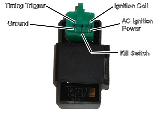
4) Blue/White: Timing trigger pulse to the CDI
5) Black/Red: AC Ignition power to the CDI
Other CDI Wires:
1) Green: Ground.
2) Black/White: Kill switch wiring. Ground this pin to kill spark, leave this pin disconnected to enable spark.
3) Black/Yellow: Ignition Coil. This is the output from the CDI that drives the ignition coil primary
...From my solenoid i have a heavy gauge Red wire on one pole that goes to the starter and on the other pole there are two wires, one heavy gauge red wire which i think would go to battery positive and a little red wire that is hooked up to the rectifier. i'm not sure if this is right. there are two wires coming out of the middle of the solenoid, a Red/Yellow and a Green/Yellow. i'm not sure if they are hooked up right but i have the Green/Yellow grounded and the Red/yellow hooked to a push button switch and then to the battery....
Your two small wires to the solenoid will work they way they are wired, but note that you no longer have the safety interlock wired in which keeps the starter from being engaged unless the brakes are applied. Without this, you will be able to start the quad in gear and no brakes applied. It could take off unexpectedly and crash into your neighbor's brand new mercedes
 .
.") ).
).Black is usually switched 12 volt power from the ignition switch (and fused, the Yellow/Green is the brake light connection and on to the the hot side of the solenoid small wires though the start button.
Two more points:
1) You *must* have an in line fuse on that small red wire to the voltage regulator. 7 amps, normal blow. It is dangerous to run a quad without a fuse. The battery can put out enough current into a short to burn up a harness in short order. The fire usually starts right under the gas tank. Fuses are cheap, so while you're rewiring things spend a coule bucks to install a fuse
 .
.2) If you don't have a kill switch, and (god forbid!) you manage to get the quad started, you will need to ground the kill switch pin on the CDI to stop the quad. There is high voltage on that pin (100 volts or so at idle - more volts at speed). Take care to ground that pin while your fingers are safely isolated from the circuit. If you have a small alligator type test clip, connect one end to a good solid ground first, then connect the other end to the CDI kill switch pin using the insulated hood between your fingers and the metal clip
Five pin CDI for reference:
#3
05-19-2011, 10:37 PM
Join Date: May 2011
Posts: 2
Likes: 0
Received 0 Likes
on
0 Posts
#4
05-20-2011, 12:06 AM
Electrical Expert
Likes High Voltage In The Tub!
Likes High Voltage In The Tub!
Join Date: Dec 2008
Location: Tracy, California, USA
Posts: 3,260
Likes: 0
Received 12 Likes
on
12 Posts

Thread
Thread Starter
Forum
Replies
Last Post
Currently Active Users Viewing This Thread: 1 (0 members and 1 guests)

