110cc basic wiring setup
#1
 10-09-2012, 08:35 PM


Join Date: Oct 2012
Posts: 4
Likes: 0
Received 0 Likes
on
0 Posts
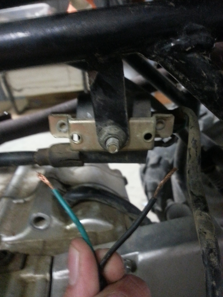
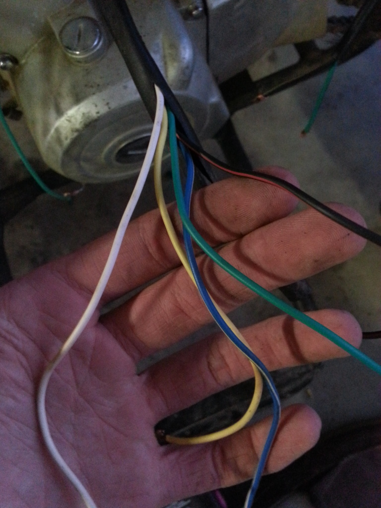
Hello I am new to this forum and ultimately new to repairing this type of engine. I work on go-karts and minibikes and they're more of the stick in and go types lol. The wiring on the quad consists of 5 wires coming out of the engine. There is a solid white wire, a solid yellow wire, a blue+white wire, a solid green wire, and a red+black wire. How do I connect all of this to the coil and magneto ect. in the pics below? I just want it to be able to have a kill switch, elec. start, and battery charge...
The existing wiring harness needs to be salvaged if at all possible!
Thanks For your Help!

The existing wiring harness needs to be salvaged if at all possible!
Thanks For your Help!
#2
10-09-2012, 10:51 PM
Join Date: Oct 2012
Posts: 4
Likes: 0
Received 0 Likes
on
0 Posts
#3
10-10-2012, 12:50 AM

Electrical Expert
Likes High Voltage In The Tub!
Likes High Voltage In The Tub!
Join Date: Dec 2008
Location: Tracy, California, USA
Posts: 3,260
Likes: 0
Received 12 Likes
on
12 Posts
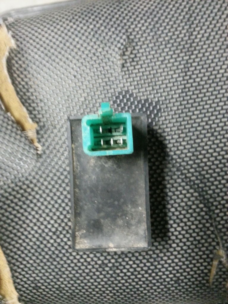
In your lifan "diagram" posted earlier I see only a four pin CDI, yet you report a five pin CDI. These are entirely different animals. Do not embark on wiring up to that lifan diagram diagram because it is wrong. The black/red wire out of your stator (you call it a magneto) is the AC ignition power which goes to your CDI, yet your diagram doesn't show any such wire going to the CDI which a 5 pin CDI must have.
Again the CDI picture in your "diagram" has four pins which guarantees it is a DC powered CDI, and with only four pins *cannot* have a kill switch input. Yet I don't see 12 volt DC power going to it, and I do see a kill switch wire going to it. This is wrong, wrong, wrong.
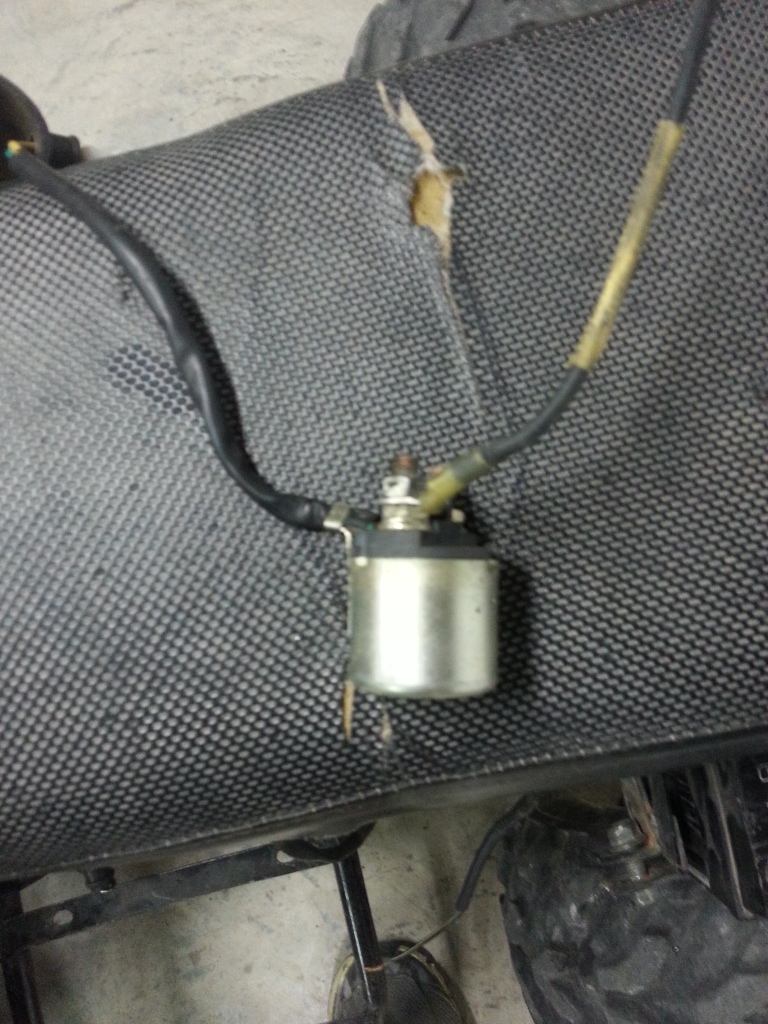
The starter solenoid wiring is unclear at best according to the "diagram".
And there is a *serious* safety issue. There is no fuse on the positive battery connection feeding all the small wires feeding the charging circuitry from the voltage regulator and the starter solenoid activation wires. This is dumb at the highest possible level. Small little quad batteries can put out over 100 amps into a short circuit, and unfused wiring can burst into flames in seconds. Don't shortcut here. Put in an in line fuse. They're cheap (found at any autoparts store). What ever you do, don't bypass this step. 7 amps - feeding everything except the big heavy wire feeding the starter motor through the starter solenoid.
Could you provide links to where you got this info from?
In your first round of pictures I didn't see any CDI. YOu do have a CDI right?
Do you have an ignition switch? Any handle bar kill switches? What about a brake switch?
Again the CDI picture in your "diagram" has four pins which guarantees it is a DC powered CDI, and with only four pins *cannot* have a kill switch input. Yet I don't see 12 volt DC power going to it, and I do see a kill switch wire going to it. This is wrong, wrong, wrong.
The starter solenoid wiring is unclear at best according to the "diagram".
And there is a *serious* safety issue. There is no fuse on the positive battery connection feeding all the small wires feeding the charging circuitry from the voltage regulator and the starter solenoid activation wires. This is dumb at the highest possible level. Small little quad batteries can put out over 100 amps into a short circuit, and unfused wiring can burst into flames in seconds. Don't shortcut here. Put in an in line fuse. They're cheap (found at any autoparts store). What ever you do, don't bypass this step. 7 amps - feeding everything except the big heavy wire feeding the starter motor through the starter solenoid.
Could you provide links to where you got this info from?
In your first round of pictures I didn't see any CDI. YOu do have a CDI right?
Do you have an ignition switch? Any handle bar kill switches? What about a brake switch?
#4
10-10-2012, 07:44 AM
Join Date: Oct 2012
Posts: 4
Likes: 0
Received 0 Likes
on
0 Posts
#5
10-10-2012, 11:10 AM
Join Date: Oct 2012
Posts: 4
Likes: 0
Received 0 Likes
on
0 Posts
#6
10-10-2012, 11:57 PM
Electrical Expert
Likes High Voltage In The Tub!
Likes High Voltage In The Tub!
Join Date: Dec 2008
Location: Tracy, California, USA
Posts: 3,260
Likes: 0
Received 12 Likes
on
12 Posts
Yes the earlier pic is your 5 pin CDI.
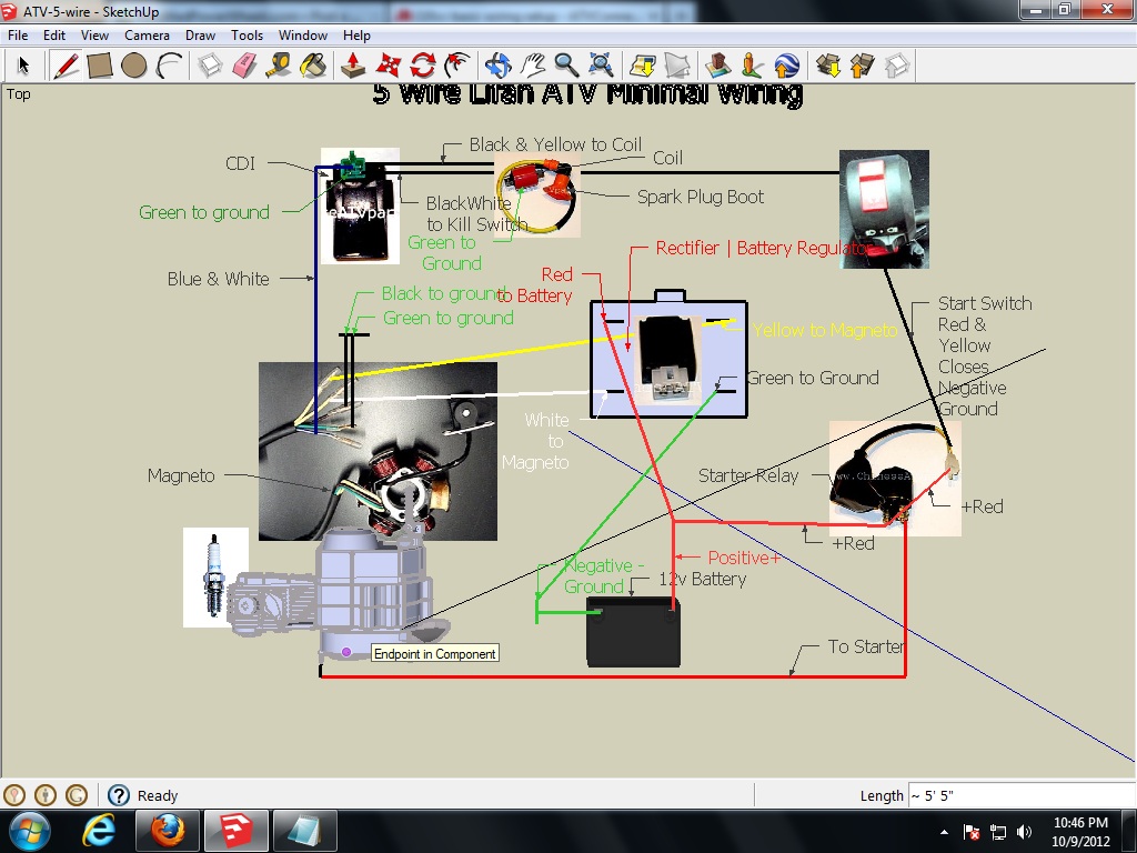
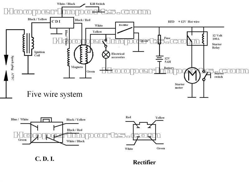
The last hooper import diagram is much closer than the the previous one, but it still has some issues. Here is a modified diagram which address the issues (click on it to make a larger version):
Attachment 6631
Note how the original diagram had all the starter motor current going through the 7 amp fuse. That won't work obviously. You'd blow the fuse everytime you pushed the start button. So in the modified diagram notice that the starter motor current (the red wires feeding the starter motor through the screw posts on the starter solenoid), and the starter ground return current (the green wires from the starter motor case back to the negative battery terminal), bypass the fuse. And this means that they have to be heavy gauge wires to handle the 35 amps or so of starter motor current. Both the green and red wires in the modified drawing should take fairly short paths, not be taped into any sort of wiring harness, and be at least #8 gauge stranded wire. All the other wiring is 18 gauge, and fed through the 7 amp fuse. Also note that I put a red "X" just above the starter solenoid input disconnecting the old path where all the starter motor current goes through the fuse. It came out kind of faint so pay attention to that.
The brake switch is used as a safety device. I drew it in in pink. Notice how it is wired. The starter solenoid actuating coil has to have 12 volts across it's two terminals before the solenoid closes and hooked the battery directly across the starter motor. So for this to happen you need:
1) A good fuse
2) The brakes have to be applied (i.e. brake switch closed)
3) And the other side of the starter solenoid actuating coil has to be grounded (via the start button) to complete the circuit.
The brake switch keeps the quad from being started up accidently in gear. You have to have the brakes applied or it won't crank the starter. This is really important with quads that have centrifical clutches since at cranking speeds the engine is disconnected from the wheels. Imagine... The quad is having trouble starting, you're feathering the throttle - trying to keep it going - then it starts to catch. You let the engine rev (yea!) and it suddenly engages the clutch and the quad lurches (whoops) out of control - smashing into something or someone.
It is like your car. You can't start up a car with the tranmission in drive for similar reasons. The results could be disasterous. Would you allow someone to rewire you car so it could start up in drive or reverse just because you have a bad neutral switch? Would you let your inexperienced teenager drive such a car? We are talking about a kids quad, right? Same thing applies.
You can just wire across the brake switch part and then there will be no safety interlock. Its up to you. Personally I would not do this. You've got a brake switch - why not use it?
One final note: The "electrical accesories" part is AC voltage roughly regulated to be the equivalent power of 12 volts DC. Things that work by getting hot (incandescant lights, choke heater) don't care if the power they receive is AC or DC as long as it it 12 volts. Make sure if you wire anything up to the yellow wire off the stator other than the regulator, that it will run on AC.
Hmmm... Do you have an electric choke (wires going to the carburator)?
#7
10-12-2012, 11:16 PM
Electrical Expert
Likes High Voltage In The Tub!
Likes High Voltage In The Tub!
Join Date: Dec 2008
Location: Tracy, California, USA
Posts: 3,260
Likes: 0
Received 12 Likes
on
12 Posts
Apparently in my last post the attachment 6631 link is broken. It works fine on my computer even now, but not from any other. I suspect that my computer is loading it from internal cache instead of the now broken link at the forum. Here is that link again:
Click on the thumbnail for a larger picture.

Click on the thumbnail for a larger picture.
Trending Topics
#8
03-01-2013, 07:08 PM

Have this ATv i think is a 110cc like brand new, that still has tips on the tires, purchased and would not turn over, replaced starter, and had no spark. Thought a lot of the wiring was after market, cut and removed wiring, ordered new engine loom. Thought I could just put back to factory and start. New loom doesn't match and I now have found out that the suspect wiring probably was as new. Made a mess of things and now need to put back wiring best I can and then find the real problem with no spark. Does anyone have a pic or another help, have a five pin CID, another connector coming out of the engine that is also a five pin connector with lesser gauge wires. Admit I have been a bonehead on this one. Any help would be greatly accepted as grace for the undeserved.
Bonehead ; don't even know what I own. VIN L4GADHL167S001576
Ps if I ca't fix. Wll sell-like new ,comes with humble pie, cheap, maybe more then cheap, might just make a Bon fire.
Bonehead ; don't even know what I own. VIN L4GADHL167S001576
Ps if I ca't fix. Wll sell-like new ,comes with humble pie, cheap, maybe more then cheap, might just make a Bon fire.
#9
03-01-2013, 11:43 PM
Electrical Expert
Likes High Voltage In The Tub!
Likes High Voltage In The Tub!
Join Date: Dec 2008
Location: Tracy, California, USA
Posts: 3,260
Likes: 0
Received 12 Likes
on
12 Posts
Drod,
In the previous post to yours there is a diagram of what you are going to need to get the quad working at a minimum. It is bare bones and something you are going to have to deal with. Wiring up a quad from scratch is a lot of work, and if you cannot find a source of factory wiring replacement looms this may be your only alternative.
I used to say that *no one* in the history of this had ever done this successfully, though I would help as best I could. Since then a few actually have succeeded - so I cannot say that anymore. But it has only been a few.
Just to leave no stone unturned, you say you have an incompatible loom that doesn't install. How incompatible is it? Does anything connect up? Does anything work? This maybe can be broken down into smaller problems, each worked on independently:
1) Getting the starter motor to turn
2) Getting spark
3) Getting the battery charging system working
4) Getting ancillary stauff working like headlights, horn, etc.
Have this ATv i think is a 110cc like brand new, that still has tips on the tires, purchased and would not turn over, replaced starter, and had no spark. Thought a lot of the wiring was after market, cut and removed wiring, ordered new engine loom. Thought I could just put back to factory and start. New loom doesn't match and I now have found out that the suspect wiring probably was as new. Made a mess of things and now need to put back wiring best I can and then find the real problem with no spark. Does anyone have a pic or another help, have a five pin CID, another connector coming out of the engine that is also a five pin connector with lesser gauge wires. Admit I have been a bonehead on this one. Any help would be greatly accepted as grace for the undeserved.
Bonehead ; don't even know what I own. VIN L4GADHL167S001576
Ps if I ca't fix. Wll sell-like new ,comes with humble pie, cheap, maybe more then cheap, might just make a Bon fire.
Bonehead ; don't even know what I own. VIN L4GADHL167S001576
Ps if I ca't fix. Wll sell-like new ,comes with humble pie, cheap, maybe more then cheap, might just make a Bon fire.
#10
03-02-2013, 03:27 AM

Range Rover
Join Date: Apr 2012
Location: only state mentioned it the bible
Posts: 194
Likes: 0
Received 0 Likes
on
0 Posts
I submit for your approval my text description of exactly what goes where I just posted here.
http://forums.atvconnection.com/chin...ml#post3171027
If I made any mistakes please comment on the thread so others will know.
This is a description of how to start from scratch and make a bike with a 5 pin cdi go w/o draining the battery. There are no lights, gages, or safety switches on this set up.