Tao Tao 200CC No Fire-Need Wiring Diagram
#1
 07-06-2011, 10:55 AM


Join Date: Jul 2011
Location: Robinson, Texas
Posts: 8
Likes: 0
Received 0 Likes
on
0 Posts
My 16YO son has a Tao Tao 250 (200CC) Quad that just quit running one day while he was sitting still idling. I have confirmed that it is getting no spark but diagnosing why has been a bit challenging. I replaced the coil and have ordered a CDI for it but beyond that (i.e. stator/magneto) I am going to need some help. Does anyone have a wiring diagram for this quad? It has a 5 wire magneto with a pink wire, a 6 pin CDI with 4pin/2 pin connectors. The starter cranks but no fire so I'm assuming all the safety switches are working properly. I tried to investigate removing the stator yesterday but the more bolts I removed, the more I realized that replacing the stator/magneto is a bit more than I care to chew until I have eliminated all other options. I would really like to have a wiring diagram with ohm values to troubleshoot further.
#2
07-06-2011, 12:55 PM

Electrical Expert
Likes High Voltage In The Tub!
Likes High Voltage In The Tub!
Join Date: Dec 2008
Location: Tracy, California, USA
Posts: 3,260
Likes: 0
Received 12 Likes
on
12 Posts
I've not seen a wiring diagram for your specific quad, but we really don't need one. Even if you had one there is a good chance it would be wrong anyway.
First things first - we need to find out if your CDI is DC powered or AC powered. They are not interchangable, and not compatible. Worse, you cannot tell for sure just by looking at them. You have to measure. Once we know what kind of CDI you have then we can follow the correct "no spark" procedure (for AC powered CDIs or DC powered CDIs).
Here is a generic procedure for finding out whether your CDI is DC or AC powered:
The 2 plug 6 wire CDIs come in two different designs. One is powered off 12 volts DC, and the other is powered off a moderately high voltage AC which comes from the stator. Unfortunately there is no reliable way to tell the difference between the two by just looking at them. To be sure you need to use a meter to find out which you have:
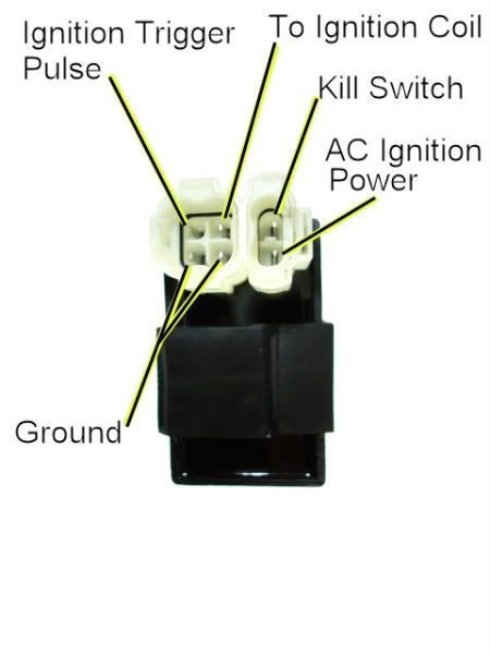
1) Unplug the CDI, and turn on the ignition. Do not crank the starter motor. Use a meter to measure the *DC* voltage on the pin labeled "AC ignition power" in the wiring harness to the ground pin in the same connector. If you measure 12 volts DC then you have a DC powered CDI.
2) If you don't measure 12 volts DC on the ignition power pin, then switch the meter over to measure AC volts on the 200 volt scale. While cranking the starter motor, measure the AC voltage on the "AC Ignition Power" pin to the the Ground pin. You should see 40 to 80 volts AC. If you measure AC voltage when the starter is turning then you have an AC powered CDI.
Using a meter is the only 100% reliable way to figure out if your CDI is AC or DC powered. But there are some clues you can use that are usually (but not always) correct:
A) DC CDIs tend to be a little larger than their AC powered counterpart. This is because the DC powered CDI needs a bunch more circuitry to convert the 12 volts DC to the moderately high voltage supply that all CDIs must have.
B) Most (but not all) DC powered quad ignition systems do not use the kill switch input pin. The CDI connector pin usually has no wire tied to it. AC powered quad ignition systems usually do use the kill switch input pin.
#3
07-06-2011, 01:34 PM
Join Date: Jul 2011
Location: Robinson, Texas
Posts: 8
Likes: 0
Received 0 Likes
on
0 Posts
Thanks. I will measure the voltages tonight and get back early tomorrow. I just hope the CDI I already ordered is correct. The website did not specify AC or DC. One thing I noticed is that some of the 6 pin have o-rings around the connector such as the one you displayed. My original and the pictured replacement do not. I wonder if there is any correlation?
#4
07-06-2011, 01:41 PM
Join Date: Jul 2011
Location: Robinson, Texas
Posts: 8
Likes: 0
Received 0 Likes
on
0 Posts
Thanks again LynnEdwards. One note of clarification. You say in step #1 you say to measure the voltage on the pin labeled "AC ignition power" to the ground pin in the same connector. Do you consider the 4 pin and 2 pin separate connectors or the same? My point is, should I measure between "AC Ignition Power and "Kill Switch" since they are in the "same connector" or will either of the ground terminals in the 4 pin connector work? I know it's minutia but I want to be clear. Also, under normal operating conditions, do the kill switches apply or remove ground from the ignition circuit?
#5
07-06-2011, 03:43 PM
Electrical Expert
Likes High Voltage In The Tub!
Likes High Voltage In The Tub!
Join Date: Dec 2008
Location: Tracy, California, USA
Posts: 3,260
Likes: 0
Received 12 Likes
on
12 Posts
Thanks again LynnEdwards. One note of clarification. You say in step #1 you say to measure the voltage on the pin labeled "AC ignition power" to the ground pin in the same connector. Do you consider the 4 pin and 2 pin separate connectors or the same? My point is, should I measure between "AC Ignition Power and "Kill Switch" since they are in the "same connector" or will either of the ground terminals in the 4 pin connector work? I know it's minutia but I want to be clear. Also, under normal operating conditions, do the kill switches apply or remove ground from the ignition circuit?
 .
.Kill switches kill the spark by applying a ground to the CDI Kill Switch pin. All kill switches in the wiring harness are wired in parallel such that if any one of them is closed the kill switch pin at the CDI is shorted to ground and the engine dies.
#6
07-06-2011, 03:49 PM
Electrical Expert
Likes High Voltage In The Tub!
Likes High Voltage In The Tub!
Join Date: Dec 2008
Location: Tracy, California, USA
Posts: 3,260
Likes: 0
Received 12 Likes
on
12 Posts
Thanks. I will measure the voltages tonight and get back early tomorrow. I just hope the CDI I already ordered is correct. The website did not specify AC or DC. One thing I noticed is that some of the 6 pin have o-rings around the connector such as the one you displayed. My original and the pictured replacement do not. I wonder if there is any correlation?
I don't think the O-rings make much difference. There is some pretty high voltage in the connectors, so one might argue that the o-rings are there to prevent water from splashing in. But the same high voltage is on the ignition coil primary, and all the kill switches (AC powered CDIs). Yet they certainly aren't protected in the same way.
#7
07-06-2011, 08:27 PM
Join Date: Jul 2011
Location: Robinson, Texas
Posts: 8
Likes: 0
Received 0 Likes
on
0 Posts
Trending Topics
#8
07-06-2011, 09:26 PM
Electrical Expert
Likes High Voltage In The Tub!
Likes High Voltage In The Tub!
Join Date: Dec 2008
Location: Tracy, California, USA
Posts: 3,260
Likes: 0
Received 12 Likes
on
12 Posts
Procedure for testing ignition systems with an AC powered CDI:
To troubleshoot no spark problems on a 6 pin AC powered CDI it makes sense to start in the middle (the CDI), measure as much as we can and branch out from there. For the CDI to do its thing it needs power, a trigger pulse, and it must must be inhibited via the kill switch input pin.
1) Unplug the CDI. Turn the ignition switch on. Set all kill switches the the "run" position. In the wiring harness, measure the resistance of the kill switch pin to the ground pin on the 20K ohm scale. It should read infinite ohms (same as when the meter leads are hanging free and not touching anything). It should not read zero ohms (shorted).
2) Leave the CDI unplugged. Use a meter to measure the resistance of the AC ignition power pin in the wiring harness to the ground wire on the 2K ohm scale. You should read approximately 400 ohms. What do you measure?
3) In a similar fashion measure the resistance of the Ignition Trigger Pulse pin to the ground pin. You should see 150 ohms or so. What do you measure?
4) Switch your meter over to measure AC volts on the 200 volt scale. Leave the CDI unplugged. While cranking the engine, measure the voltage on the AC Ignition Power pin in the wiring harness to the ground pin. You should measure 40 to 80 volts AC. What do you measure?
5) Set your meter down to the lowest scale you have for measuring AC volts. 2 volts would be ideal, but some meters don't go that low. In that case use the lowest scale you have. While cranking the engine, measure the voltage on the Ignition Trigger Pulse pin in the wiring harness to the ground pin. You should measure 0.2 to 0.5 volts AC. What do you measure?
6) Now plug the CDI back in. Measure the AC voltage on the Ignition Coil pin to the ground pin using the 200 volt scale. If you have to, use a sewing pin to poke through the wire insulation and then put the meter probe on the sewing pin. But don't hold your fingers on the connection during the next test - there may be high voltage here when the engine is turning. With the ignition on and all kill switches set to the "run" position, crank the starter motor. You should see voltages bouncing around at random values and the meter captures all or part of a spark event. What do you see?
#9
07-07-2011, 03:39 PM
Join Date: Jul 2011
Location: Robinson, Texas
Posts: 8
Likes: 0
Received 0 Likes
on
0 Posts
Thanks again LynnEdwards. It was last last night when I got your reply but I just could not stand to wait. I printed your response and went to work in my 90 degree Texas garage at 10:00 p.m. mind you). Curiously, I saw that the kill switch pin had zero ohms to ground. I started fidgeting with the kill switch and it went to infinity (good thing). I took a few more measurements all except the last step) per your guide and recorded them but forgot them at home. At any rate, they seemed to be within a reasonable tolerance of the values you gave me. After I got the kill switch to go to infinity, I did plug in the CDI. I just knew it was going to start but to no avail. I will be doing this check again when I get home but I am starting to suspect the kill switch no for obvious reasons. It's acting rather squirly. I will be posting later this evening. Hope to hear from you then or better yet, I hope to tell you I have it running!
One other thing is that my cheap a%$ multimeter only goes down to 200VAC so seeing 200mV is difficult. I did however see about 0.1V on the display. Given that it is a cheap meter with likely poor accuracy, I will think that this is sufficient to say it is good.
Tim
One other thing is that my cheap a%$ multimeter only goes down to 200VAC so seeing 200mV is difficult. I did however see about 0.1V on the display. Given that it is a cheap meter with likely poor accuracy, I will think that this is sufficient to say it is good.
Tim
#10
07-09-2011, 04:37 PM
Join Date: Jul 2011
Location: Robinson, Texas
Posts: 8
Likes: 0
Received 0 Likes
on
0 Posts
LynnEdwards,
I finally had some time to troubleshoot the CDI with your directions and a decent meter. The results are:
1. Kill Switch Pin to ground = infinite ohms
2. AC ignition Power pin to ground = 280 ohms
3. Ignition Trigger Pulse to ground = 155 ohms
4. AC Ignition Power pin to ground while cranking = 61mVAC
5. Ignition trigger pulse pin to ground while cranking = 180mVAC
6. CDI plugged in. Ignition coil pin to ground while cranking = 0VAC
What's your opinion?
Thanks,
Tim-