Kazuma Falcon 110 ignition wiring
#1
 06-05-2011, 09:39 PM


Hi all,
I just picked up a Kazuma Falcon 110. The vin number has a 5 as the 10th digit, so I think I am dealing with a 2005 machine. The wiring is all messed up and I would like to try to get it running. I have looked for wiring diagrams, but I have not found one that has the colors of all the wires that mine has. This machine has lights and a horn as well as a LED panel to show what gear you are in.
The previous owner lost the key and took the ignition out, so I really need to know how to wire that up. I removed the cylinder from the ignition and am going to see if somewhere like Home Depot can just make a key to work. The problem is I had to disassemble the unit to get the cylinder out and now I'm not sure which way to put it back together. The way the cylinder fits I have two options that are 180 degrees apart. The wires coming out of the ignition are:
Red, Black, Black/White, Yellow, Yellow/white, and Green. Can anybody tell me which ones should have continuity when the switch is turned from off to on then on with lights? Also a full wiring diagram with instructions how to read it?
Thanks
Nik
#2
06-07-2011, 12:23 AM

Electrical Expert
Likes High Voltage In The Tub!
Likes High Voltage In The Tub!
Join Date: Dec 2008
Location: Tracy, California, USA
Posts: 3,260
Likes: 0
Received 12 Likes
on
12 Posts
I have never seen a 6 wire ignition switch.
Four of the colors seem to be pretty standard. The yellow and yellow white have me a bit confused:
1) Red: I'm betting this is fused 12 volts (12 volts direct from the battery through a fuse). Measure this with a meter. It should have 12 volts on it all the time relative to ground.
2) Green: Ground. Measure the resistance of this wire to engine ground. It should be zero ohms.
3) Black: Switched 12 volts. This should have 12 volts on it whenever the ignition switch is on.
4) Black/White: Kill switch. This wire should have zero ohms to ground when any kill switch is activated (like the handlebar kill switch, or a rear tether if you have one). The ignition switch normally is one of the kill switches too - this is what kills the engine when you turn the ignition switch "off"
Again, yellow and yellow/white are a mystery. Look all over your wiring harness. Where else do you see a yellow wire? Where else do you see a yell/white wire? What do they hook to? These are clues. Important: Only pay attention to colors in the main taped up wiring harness. Ignore the colors of short pigtail wires going to the components themselves. The idea is that a pink wire with white polkadots (for example) entering the taped up wiring harness will still be pink with white polkadots wherever it comes back out. By looking at the wire source and destination the wire function can be surmized, and the jigsaw like puzzle starts to come together.
#3
06-07-2011, 08:25 PM
Thanks for the reply. I'm just surprised that nobody has an accurate diagram for this ATV seeing as it has been around a while and Kazuma is one of the more popular Chinese ATV's
I'm thinking that the yellows must have something to do with the lights because on my 50cc Kazuma the key is one position for on and another for on with lights.
If I just wanted to hotwire it without using the ignition, then how would I go about doing that? I want to see if I can get this thing running first before I dump money into fixing it up the right way.
Like I said, it has a bunch of messed up wiring at the battery. It has the main black and red wires that obviously go to the battery, but then there are some other random red wires and one other one with what looks like it held one end of a fuse at some point. Might be the fused power wire to the ignition. Do those main wires basically go to the starter solenoid because it draws the most juice?
Thanks again
Nik
#4
06-08-2011, 12:18 AM
Electrical Expert
Likes High Voltage In The Tub!
Likes High Voltage In The Tub!
Join Date: Dec 2008
Location: Tracy, California, USA
Posts: 3,260
Likes: 0
Received 12 Likes
on
12 Posts
Wiring diagrams are often not available for a lot of chinese quads. I had to trace out my entire wire diagram myself (it is not a kazuma). Even when you do get a wire diagram they are often not current, and riddled with errors.
I was going to ask if your ignition switch had three positions, but it looks like you answered it. I was thinking that the three positions were off, on, and start - but on with lights make even more sense considering the wire colors. I'm guesstimating that your lights are AC powered direct off the stator. If so yellow would be AC from the stator, Yellow/White would be switch AC to the headlights.
All this is based on standard color codes. Most quads use one of a few standard color schemes, but this is no guarantee. If your going to start hooking stuff up to try it you *must* have a fuse in line with the battery feeding all 12 volts (red wires) stuff except the fat heavy wire to the solenoid (and on to the starter motor on the other side of the solenoid). 7 amps is the standard value.
Once you have the fuse in place I would try shorting the red and black wires, leave all the others open (disconnected). Try to start the quad.
If the quad doesn't start try jumping across the solenoid and see if it starts.
To kill the quad engine (should it start right up ), use the handle bar kill switch. If that doesn't work short the green and Black/white wire together. *CAUTION* there is high voltage on the black white wire when the engine is running (or cranking). Mind you fingers when shorting it to ground.
I was going to ask if your ignition switch had three positions, but it looks like you answered it. I was thinking that the three positions were off, on, and start - but on with lights make even more sense considering the wire colors. I'm guesstimating that your lights are AC powered direct off the stator. If so yellow would be AC from the stator, Yellow/White would be switch AC to the headlights.
All this is based on standard color codes. Most quads use one of a few standard color schemes, but this is no guarantee. If your going to start hooking stuff up to try it you *must* have a fuse in line with the battery feeding all 12 volts (red wires) stuff except the fat heavy wire to the solenoid (and on to the starter motor on the other side of the solenoid). 7 amps is the standard value.
Once you have the fuse in place I would try shorting the red and black wires, leave all the others open (disconnected). Try to start the quad.
If the quad doesn't start try jumping across the solenoid and see if it starts.
To kill the quad engine (should it start right up
), use the handle bar kill switch. If that doesn't work short the green and Black/white wire together. *CAUTION* there is high voltage on the black white wire when the engine is running (or cranking). Mind you fingers when shorting it to ground.
#5
06-08-2011, 08:16 PM
Thanks again, Lynn. I put the ignition switch back together. In the off position there is continuity between black/white and ground. First position closes the red/black circuit and opens bl/wh to ground. Last position keeps red/black closed and also makes the circuit between yellow and yellow/white. Sounds like you were spot on! The previous owner melted the 6-pin connector when he pigtailed everything together, so I will have to hook it up with some wire nuts temporarily.
Will an automotive blade type fuse be OK for the fuse? How about 7.5A because I have some of those around.
I am going to have to take a look at the whole wiring setup when I get more time. It is in my shed right now with no room around it to work. Too much junk I need to get rid of.
Will an automotive blade type fuse be OK for the fuse? How about 7.5A because I have some of those around.
I am going to have to take a look at the whole wiring setup when I get more time. It is in my shed right now with no room around it to work. Too much junk I need to get rid of.
#6
06-08-2011, 11:37 PM
Electrical Expert
Likes High Voltage In The Tub!
Likes High Voltage In The Tub!
Join Date: Dec 2008
Location: Tracy, California, USA
Posts: 3,260
Likes: 0
Received 12 Likes
on
12 Posts
Sounds like the switch is working exactly as it should. And it sounds like the wire colors are indeed standard. That makes things a little easier.
A blade type 7.5 amp fuse is perfect. A ten amp fuse is OK too. A 20 or 30 amp fuse is not OK. The idea is to make sure that a sustained (and errant) current load at or just below the rated fuse value will not damage/melt the wiring harness without blowing the fuse first.
A blade type 7.5 amp fuse is perfect. A ten amp fuse is OK too. A 20 or 30 amp fuse is not OK. The idea is to make sure that a sustained (and errant) current load at or just below the rated fuse value will not damage/melt the wiring harness without blowing the fuse first.
#7
06-12-2011, 11:56 PM
OK, I've been tinkering with the wiring. I know the solenoid has two main posts that connect to the battery and the starter motor. You can jump these to start the motor. But my solenoid (not stock I don't think) has two other smaller wires as well. I know that these are the wires that will make the coil inside energize and pull the contacts for the large posts together thus starting the motor. But what do I hook these up to?
I have a red/yellow wire that comes from the starter button that I think plays a role here, but which side do I hook it to? Also, I'm not sure if this red/yellow wire is carrying +12v or if it is ground. I took the handlebar switch apart and the on/off handlebar switch has two green and one black/white wire. Black/white I know is kill, one green comes in and the other green goes to the starter button. When contact is made on the starter button, it connects green from the switch with the red/yellow wire. This makes me think that the starter button is completing the circuit on the ground side, not the +12v side. Does the solenoid get one +12v and ground? And if so, then where do I get the +12v from? Help.
Thanks
Trending Topics
#8
06-13-2011, 10:37 AM
Electrical Expert
Likes High Voltage In The Tub!
Likes High Voltage In The Tub!
Join Date: Dec 2008
Location: Tracy, California, USA
Posts: 3,260
Likes: 0
Received 12 Likes
on
12 Posts
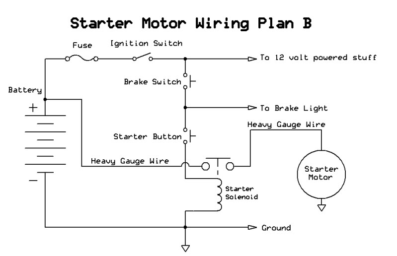
There are two common methods for wiring up the starter solenoid in chinese quads:
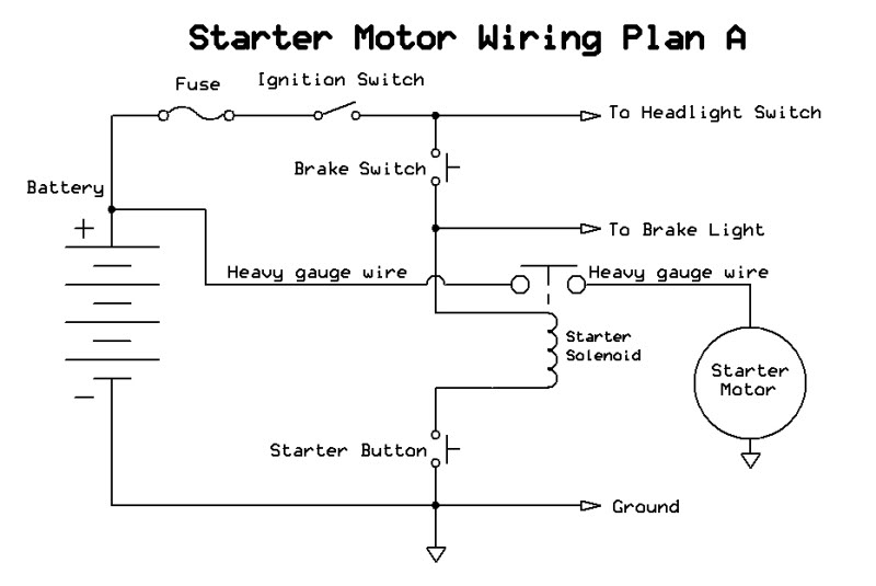
Everything you described (right down to the same wire colors as my quad) suggests you have Plan A where the ground is applied to the solenoid actuating coil through the starter button. The other side of the solenoid actuating coil gets 12 volts through the brake switch, ignition switch and fuse. This safety interlock keeps the quad from starting unless the brakes are applied so it won't take off unexpectedly if it is in gear.
Verify the above by measuring the solenoid coil resistance to ground with the ignition off, It should be open, then when you push the starter button the resistance will drop to zero on one side of the solenoid coil, or 4-6 ohms for the other side (you're measuring ground through the resistance of the solenoid coil).
#9
06-13-2011, 08:44 PM
Thanks Lynn. I am in the process of reconnecting several things right now, so I don't know if I will be able to perform those tests as of yet.
I'm assuming that the polarity does matter for the coil, so I am going to try to bench test the coil by applying 12v across the two "trigger" connections. Will the coil only work one way? For instance, if I hook + to one side and - to the other and the two heavy posts shoe continuity, then can I assume this is the correct polarity? The solenoid won't work if it is connected backwards, right?
I'm assuming that the polarity does matter for the coil, so I am going to try to bench test the coil by applying 12v across the two "trigger" connections. Will the coil only work one way? For instance, if I hook + to one side and - to the other and the two heavy posts shoe continuity, then can I assume this is the correct polarity? The solenoid won't work if it is connected backwards, right?
#10
06-14-2011, 12:01 AM
Electrical Expert
Likes High Voltage In The Tub!
Likes High Voltage In The Tub!
Join Date: Dec 2008
Location: Tracy, California, USA
Posts: 3,260
Likes: 0
Received 12 Likes
on
12 Posts
Thanks Lynn. I am in the process of reconnecting several things right now, so I don't know if I will be able to perform those tests as of yet.
I'm assuming that the polarity does matter for the coil, so I am going to try to bench test the coil by applying 12v across the two "trigger" connections. Will the coil only work one way? For instance, if I hook + to one side and - to the other and the two heavy posts shoe continuity, then can I assume this is the correct polarity? The solenoid won't work if it is connected backwards, right?
I'm assuming that the polarity does matter for the coil, so I am going to try to bench test the coil by applying 12v across the two "trigger" connections. Will the coil only work one way? For instance, if I hook + to one side and - to the other and the two heavy posts shoe continuity, then can I assume this is the correct polarity? The solenoid won't work if it is connected backwards, right?
When you're doing your experiments keep in mind that the solenoid is a short term operating device. When activated the internal coil is dissapating about 25-36 watts in heat so it will warm up quickly. Don't leave the solenoid closed (clicked in) for more than a minute at a time, and allow it to cool before repeating. You can tell if your overdoing it by feeling the solenoid case.