Hanma 110cc wiring problems
#1
 12-11-2010, 10:22 AM


Join Date: Dec 2010
Posts: 13
Likes: 0
Received 0 Likes
on
0 Posts
Hi, Im new here, but have been lurking for awhile. I just recently aquired two Sunl Hanma 110cc for free.The guy i got them from is tired of working on the electrical problems that they seemed to be plagued with. my question is, is there a way to make these things more reliable with just a basic wiring diagram. I have opened up the wire harness and lets just say its a mess.
the PO hacked a lot of wiring and didnt solder anything back together I just want to gut the whole thing and start new, but cant seem to find a simple diagram, without all the remote start and kill I just want a on/off and kill switch. maybe someone on here can direct me in the right direction. I want to get them running before christmas so I can give them to my two boys as presents.
  I have a little bit of wiring knowledge, but rely a lot on my Dad who is an Electrical engineer. oh they have the 4 pin CDI in them if that helps
my question is, is there a way to make these things more reliable with just a basic wiring diagram. I have opened up the wire harness and lets just say its a mess.the PO hacked a lot of wiring and didnt solder anything back together
I just want to gut the whole thing and start new, but cant seem to find a simple diagram, without all the remote start and kill I just want a on/off and kill switch. maybe someone on here can direct me in the right direction. I want to get them running before christmas so I can give them to my two boys as presents. I have a little bit of wiring knowledge, but rely a lot on my Dad who is an Electrical engineer. oh they have the 4 pin CDI in them if that helps
#2
12-11-2010, 05:39 PM
Hi, Im new here, but have been lurking for awhile. I just recently aquired two Sunl Hanma 110cc for free.The guy i got them from is tired of working on the electrical problems that they seemed to be plagued with. my question is, is there a way to make these things more reliable with just a basic wiring diagram. I have opened up the wire harness and lets just say its a mess.
the PO hacked a lot of wiring and didnt solder anything back together I just want to gut the whole thing and start new, but cant seem to find a simple diagram, without all the remote start and kill I just want a on/off and kill switch. maybe someone on here can direct me in the right direction. I want to get them running before christmas so I can give them to my two boys as presents. I have a little bit of wiring knowledge, but rely a lot on my Dad who is an Electrical engineer. oh they have the 4 pin CDI in them if that helps
my question is, is there a way to make these things more reliable with just a basic wiring diagram. I have opened up the wire harness and lets just say its a mess.the PO hacked a lot of wiring and didnt solder anything back together
I just want to gut the whole thing and start new, but cant seem to find a simple diagram, without all the remote start and kill I just want a on/off and kill switch. maybe someone on here can direct me in the right direction. I want to get them running before christmas so I can give them to my two boys as presents. I have a little bit of wiring knowledge, but rely a lot on my Dad who is an Electrical engineer. oh they have the 4 pin CDI in them if that helpsChinese ATV 110 Wiring Diagram
LynnEdwards may have the exact diagram. i don't know..

#3
12-11-2010, 06:53 PM
Join Date: Dec 2010
Posts: 13
Likes: 0
Received 0 Likes
on
0 Posts
Thanks Jaster94 that is helpful, the problem with the current wiring is that its been so hacked that I dont know whats going oneach wire has been spliced into, then just electrical tape over that. I just want to start over. I want to know how to wire in kill and on/off switch, has anybody just rewired these with good results. the only way to get it to turn over now is to jumper the two posts on top of the starter solenoid. but no spark, I had a moto shop check my coil and its good. the current wiring is such a rats nest that I just want to gut it and rewire the basics without the remote and tether. any help is much appreciated.
each wire has been spliced into, then just electrical tape over that. I just want to start over. I want to know how to wire in kill and on/off switch, has anybody just rewired these with good results. the only way to get it to turn over now is to jumper the two posts on top of the starter solenoid. but no spark, I had a moto shop check my coil and its good. the current wiring is such a rats nest that I just want to gut it and rewire the basics without the remote and tether. any help is much appreciated.
#4
12-11-2010, 09:17 PM

Electrical Expert
Likes High Voltage In The Tub!
Likes High Voltage In The Tub!
Join Date: Dec 2008
Location: Tracy, California, USA
Posts: 3,260
Likes: 0
Received 12 Likes
on
12 Posts
Completely rewiring a quad is a big job. I would really try to fix up the old harness rather than starting over.
The wiring diagram that Jaster94 posted is for a 5 wire AC powered CDI. You have a 4 pin DC powered CDI. Here is a wiring diagram from www.HighRPMRacer.com for a 4 pin CDI:
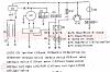
Note that item (7) is listed as a brake switch, but in fact it is a kill switch. Also note there are two item (8)'s. The small one is the main fuse, and the bigger one is the ignition switch. It is very rare to find a quad wiring diagram that doesn't have errors. (Item 14 is listed as the front tail light - that's funny ... )
If I were attacking this problem I would divide up all the wiring problems into smaller chunks and solve them one chunk at a time (divide and conquer):
1) Get the quad to produce spark: For the time being jump the solenoid to turn the engine.
2) Get the starter motor to turn over with the start button through the brake safety interlock.
3) Get the battery charging system working so your battery won't go dead as you ride.
4) Get any ancillary stuff working such as headlights, horn, etc.
You'll need a meter of course.
I have a simplified diagram of the ignition system on a 4 pin CDI quad that I drew up a while back. Let me see if I can find it and post it later tonight.
The wiring diagram that Jaster94 posted is for a 5 wire AC powered CDI. You have a 4 pin DC powered CDI. Here is a wiring diagram from www.HighRPMRacer.com for a 4 pin CDI:
Note that item (7) is listed as a brake switch, but in fact it is a kill switch. Also note there are two item (8)'s. The small one is the main fuse, and the bigger one is the ignition switch. It is very rare to find a quad wiring diagram that doesn't have errors. (Item 14 is listed as the front tail light - that's funny ... )
If I were attacking this problem I would divide up all the wiring problems into smaller chunks and solve them one chunk at a time (divide and conquer):
1) Get the quad to produce spark: For the time being jump the solenoid to turn the engine.
2) Get the starter motor to turn over with the start button through the brake safety interlock.
3) Get the battery charging system working so your battery won't go dead as you ride.
4) Get any ancillary stuff working such as headlights, horn, etc.
You'll need a meter of course.
I have a simplified diagram of the ignition system on a 4 pin CDI quad that I drew up a while back. Let me see if I can find it and post it later tonight.
#5
12-11-2010, 09:38 PM
Join Date: Dec 2010
Posts: 13
Likes: 0
Received 0 Likes
on
0 Posts
#6
12-11-2010, 10:00 PM
Electrical Expert
Likes High Voltage In The Tub!
Likes High Voltage In The Tub!
Join Date: Dec 2008
Location: Tracy, California, USA
Posts: 3,260
Likes: 0
Received 12 Likes
on
12 Posts
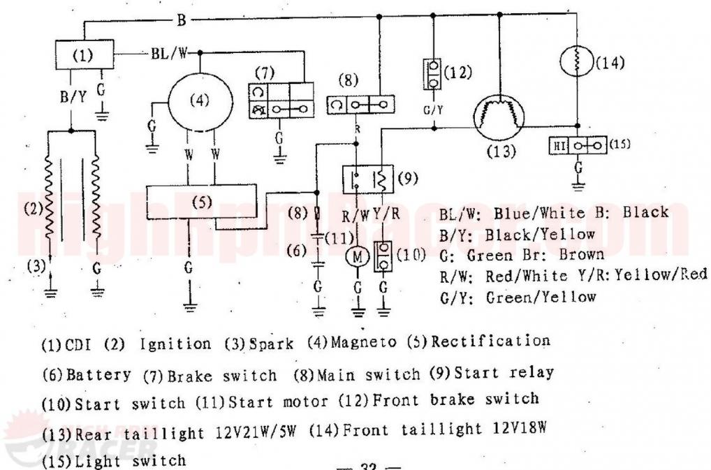
Ok, lets see if I can get the simplified 4 pin CDI ignition diagram up:
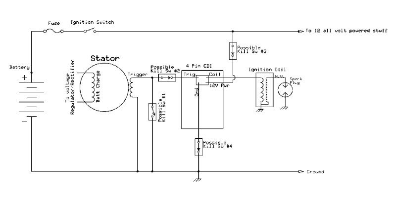
And here is a pic of a typical four pin CDI:
In the simplified wiring diagram note that there are four kill switches drawn in. These outline all the common ways of wiring a kill switch on a DC powered ignition system. You may have more than one of these wired in (handlebar kill switch plus a tether kill switch, for example), or even none (besides the ignition switch). The ignition switch is a kill switch since it removes power from the CDI.
The four possible kill switch wiring schemes:
Kill Switch #1: Short the Timing Trigger signal from the stator pickup coil to ground. If there is no trigger signal the CDI doesn't fire and the quad engine stops. The HighRPMRacer wiring diagram in the last post uses this method to stop the quad engine when you push the left handlebar kill switch.
Kill Switch #2: Disconnect the trigger signal from the CDI. If no trigger reaches the CDI there will be no spark and the engine stops.
Kill Switch #3: This switch removes power from the CDI. CDI's cannot produce spark with no power so the engine dies.
Kill Switch #4: This switch remove the ground to the CDI. CDI's don't work without a ground, so the engine dies.
Again, you will not need nor have all of these kill methods wired in. The switches in the diagram are shown in the "engine running" condition. Thus all switches shown connected (#2 thru #4) can be replaced with a wire if not used. All switches shown disconnected (#1) can be just left out.
#7
12-12-2010, 08:35 AM
Trending Topics
#8
12-12-2010, 11:50 AM
Electrical Expert
Likes High Voltage In The Tub!
Likes High Voltage In The Tub!
Join Date: Dec 2008
Location: Tracy, California, USA
Posts: 3,260
Likes: 0
Received 12 Likes
on
12 Posts
. In fact you were the one who sent me the link for the 4 pin CDI quad wiring diagram a while back which has proved very useful.
#9
12-12-2010, 12:06 PM
Electrical Expert
Likes High Voltage In The Tub!
Likes High Voltage In The Tub!
Join Date: Dec 2008
Location: Tracy, California, USA
Posts: 3,260
Likes: 0
Received 12 Likes
on
12 Posts
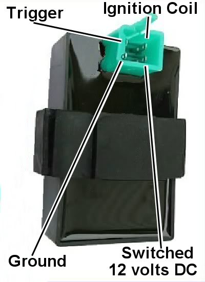
On your starter motor problem here are two simplified diagrams showing how the start circuitry is wired up:
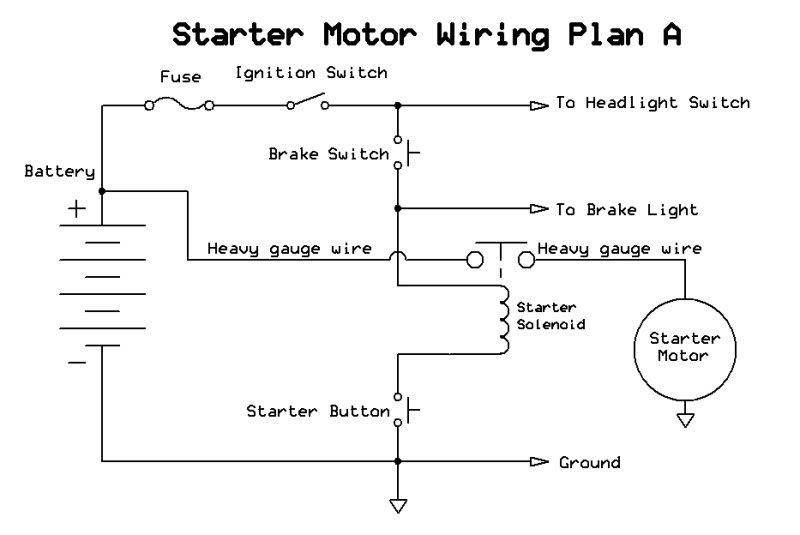
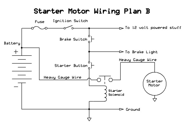
The quad wiring diagram I posted earlier uses Plan A, but 110cc quads more commonly use plan B. Plan B allows for remote modules to be wired up easier, so if your quads had a remote module option then you will probably find the starter circuitry is wired as plan B.
The operation is basically the same. To engage the starter motor you need to have 12 volts applied across the starter solenoid actuating coil. The current in the coil generates a magnetic field that sucks down a steel plate which shorts the two solenoid posts together - just like when you jump the solenoid with a screwdriver.
For plan B, one side of the solenoid actuating coil is grounded all the time. 12 volts is applied to the other side of the coil through the:
1) Fuse
2) Ignition switch
3) Brake switch (brake light must be "on")
4) Start button
For plan A, 12 volts gets to one side of the actuating coil through the:
1) Fuse
2) Ignition switch
3) Brake switch (brake light must be "on")
But the actuating coil needs a ground before the circuit is complete. When you push the start button the other side of the actuating coil gets grounded and the circuit is complete.
#10
12-12-2010, 01:30 PM
Join Date: Dec 2010
Posts: 13
Likes: 0
Received 0 Likes
on
0 Posts
Lynn thanks once again for making this soo much eaiser on me. all this helps so much. I keep finding cut/ or open wires in this whole mess but I am narrowing it down. I think the problem with non cranking is the brake switch, I think I might just start with new wires and wire it the way it shows on the diagram. there are just to many broke or cut wires in one of the quads the other one is pretty unmolested when it comes to the harness. I will use that one to copy. I cant Thank you enough I will tackle these more tonight with my Dad. also in your diagram's you show fuses mine have none what amp fuse's should I be using? Thanks Once again for all the help!!!

